Toyota 4Runner: Accumulator Low Pressure (C1256)
DESCRIPTION
Refer to DTC C1254 (See page .gif) ).
).
|
DTC Code |
DTC Detection Condition |
Trouble Area |
|---|---|---|
|
C1256 |
The fluid pressure inside the accumulator is below the standard value. |
|
CAUTION / NOTICE / HINT
NOTICE:
When replacing the master cylinder solenoid, perform calibration (See page
).
HINT:
When DTC C1251, C1253 or C1254 is output together with DTC C1256 inspect and repair the trouble area indicated by DTC C1251, C1253 or C1254 first.
PROCEDURE
|
1. |
RECONFIRM DTC |
(a) Clear the DTCs (See page ).
(b) Turn the ignition switch off.
(c) Depress the brake pedal 20 times or more.
(d) Turn the ignition switch to ON.
(e) Wait for 99 seconds.
(f) Check if the same DTC is output (See page
).
|
Result |
Proceed to |
|---|---|
|
DTC is output |
A |
|
DTC is not output |
B |
HINT:
Excessive brake pedal operation results in abnormal accumulator pressure consumption. This is normal.
| B | .gif) |
USE SIMULATION METHOD TO CHECK |
|
.gif)
|
2. |
INSPECT HYDRAULIC BRAKE BOOSTER ASSEMBLY FUNCTION |
(a) Inspect brake booster pump power supply system function.
(1) Turn the ignition switch off.
(2) Depress the brake pedal 20 times or more to release the pressure in the accumulator.
HINT:
When the pressure is released, the brake pedal stroke becomes longer.
(3) Check that the brake fluid level is at the MAX level.
(4) Chock the 4 wheels and release the parking brake.
(5) Turn the ignition switch to ON and measure the brake booster pump operating time (the time from when the brake booster pump starts operating until it stops).
OK:
20 to 80 seconds
(6) Start the engine after the brake boost pump stops.
(7) Check that the ABS warning light and slip indicator light are not illuminated.
(8) Turn off the engine, and then turn the ignition switch to ON.
(9) Check that the brake boost pump operates and then stops when the brake pedal is depressed 4 or 5 times.
(10) Depress the brake pedal 4 or 5 times and measure the brake booster pump operating time (the time from when the brake booster pump starts operating until it stops).
OK:
2 to 11 seconds
(11) Check that the brake warning light illuminates and the buzzer sounds when the brake pedal is fully depressed continuously 15 to 20 times.
NOTICE:
Wait 120 seconds or more after turning the ignition switch to ON before performing this inspection.
(b) Check brake booster operation.
(1) Turn the ignition switch off.
(2) Depress the brake pedal 20 times or more to release the pressure in the accumulator.
HINT:
When the pressure is released, the brake pedal stroke becomes longer.
(3) Depress the brake pedal, start the engine, and check the change in the brake pedal height.
OK:
The brake pedal moves slightly inward.
(c) Inspect brake master cylinder fluid pressure change (See page
).
| NG | |
GO TO STEP 5 |
|
|
3. |
READ VALUE USING TECHSTREAM (ACCUMULATOR SENSOR) |
(a) Turn the ignition switch off.
(b) Connect the Techstream to the DLC3.
(c) Turn the ignition switch to ON.
(d) Turn the Techstream on.
(e) Enter the following menus: Chassis / ABS/VSC/TRAC / Data List.
ABS/VSC/TRAC|
Tester Display |
Measurement Item/Range |
Normal Condition |
Diagnostic Note |
|---|---|---|---|
|
Accumulator Sensor |
Accumulator pressure sensor reading/ Min.: 0.00 V, Max.: 5.00 V |
3.58 to 5 V |
If the value is constant regardless of the pump operation, an accumulator pressure sensor malfunction is suspected. |
(f) Check that the accumulator output value is normal.
OK:
Accumulator pressure sensor value is normal.
| NG | |
REPLACE MASTER CYLINDER SOLENOID |
|
|
4. |
RECONFIRM DTC |
(a) Clear the DTCs (See page ).
(b) Turn the ignition switch off.
(c) Check if the same DTC is output (See page
).
|
Result |
Proceed to |
|---|---|
|
DTC is output |
A |
|
DTC is not output |
B |
| A | |
REPLACE MASTER CYLINDER SOLENOID |
| B | |
USE SIMULATION METHOD TO CHECK |
|
5. |
INSPECT BRAKE BOOSTER PUMP ASSEMBLY |
(a) Remove the hydraulic brake booster assembly (See page
).
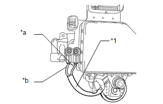
(b) Using a screwdriver, remove the 2 screws and pull out the wire harness from the master cylinder solenoid.
|
(c) Measure the resistance according to the value(s) in the table below. Standard Resistance:
|
|
(d) Install the pump motor wire harness to the master cylinder solenoid with the 2 screws.
Torque:
2.9 N·m {30 kgf·cm, 26 in·lbf}
| OK | |
REPLACE HYDRAULIC BRAKE BOOSTER ASSEMBLY |
| NG | |
REPLACE BRAKE BOOSTER WITH ACCUMULATOR PUMP ASSEMBLY |
 Pressure Sensor or Switch (C1254)
DESCRIPTION
The accumulator pressure sensor is connected to the skid control ECU in the master
cylinder solenoid.
DTC Code
DTC Detection Condition
Trouble Area
...
 Power Supply Drive Circuit (C1257)
DESCRIPTION
The motor relay (semiconductor relay) is built into the master cylinder solenoid
and drives the pump motor based on a signal from the skid control ECU.
DTC Code
D ...
Other materials about Toyota 4Runner:
Speaker Circuit
DESCRIPTION
If there is a short in a speaker circuit, the stereo component amplifier
assembly detects it and stops output to the speakers.
Thus sound cannot be heard from the speakers even if there is no malfunction
in the stereo component ...
No Communication in Immobiliser System (B2796,B2798)
DESCRIPTION
DTC B2796 is stored when a key is inserted into the ignition key cylinder
but no communication occurs between the key and transponder key ECU assembly.
DTC B2798 is stored when a key is inserted into the ignition key cylinder
...
0.0072