Toyota 4Runner: Adjustment
ADJUSTMENT
CAUTION / NOTICE / HINT
.png)
HINT:
- Centering bolts are used to mount the door hinge to the vehicle body and door. The door cannot be adjusted with the centering bolts installed. Substitute the centering bolts with standard bolts when making adjustments.
- The specified torque for standard bolts is shown in the standard bolt
chart (See page
.gif) ).
).
PROCEDURE
1. INSPECT REAR DOOR
(a) Check that the clearance measurements of areas A through H are within each standard range.
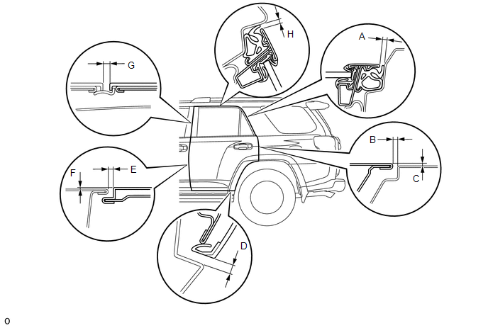
Standard:
|
Area |
Measurement |
Area |
Measurement |
|---|---|---|---|
|
A |
3.9 to 6.9 mm (0.154 to 0.272 in.) |
B |
3.0 to 6.0 mm (0.118 to 0.236 in.) |
|
C |
-1.5 to 1.5 mm (-0.0591 to 0.0591 in.) |
D |
5.5 to 8.5 mm (0.217 to 0.335 in.) |
|
E |
3.3 to 6.3 mm (0.130 to 0.248 in.) |
F |
-1.5 to 1.5 mm (-0.0591 to 0.0591 in.) |
|
G |
3.4 to 6.4 mm (0.134 to 0.252 in.) |
H |
4.1 to 7.0 mm (0.161 to 0.276 in.) |
2. DISCONNECT CABLE FROM NEGATIVE BATTERY TERMINAL
NOTICE:
When disconnecting the cable, some systems need to be initialized after the cable
is reconnected (See page ).
3. ADJUST REAR DOOR
|
(a) Using SST, loosen the hinge bolts on the vehicle body and adjust the door position. SST: 09812-00010 |
|
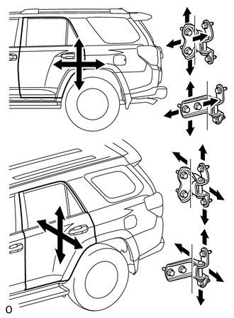
(b) Tighten the hinge bolts on the vehicle body after the adjustment.
Torque:
26 N·m {265 kgf·cm, 19 ft·lbf}
(c) Loosen the hinge bolts on the door and adjust the door position.
(d) Tighten the hinge bolts on the door after the adjustment.
Torque:
27 N·m {275 kgf·cm, 20 ft·lbf}
|
(e) Using a T40 "TORX" socket wrench, slightly loosen the striker mounting screws. |
|
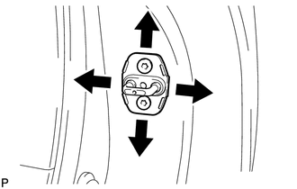
(f) Using a brass bar and hammer, hit the striker to adjust its position.
(g) Using a T40 "TORX" socket wrench, tighten the striker mounting screws after the adjustment.
Torque:
23 N·m {235 kgf·cm, 17 ft·lbf}
4. CONNECT CABLE TO NEGATIVE BATTERY TERMINAL
NOTICE:
When disconnecting the cable, some systems need to be initialized after the cable
is reconnected (See page ).
5. INSPECT SRS WARNING LIGHT
(See page )
 Disassembly
DISASSEMBLY
CAUTION / NOTICE / HINT
HINT:
Use the same procedure for both the RH and LH sides.
The procedure listed below is for the LH side.
PROCEDURE
1. DISCONNECT CABLE FROM ...
 Reassembly
REASSEMBLY
CAUTION / NOTICE / HINT
HINT:
Use the same procedure for both the RH and LH sides.
The procedure listed below is for the LH side.
PROCEDURE
1. INSTALL NO. 3 OUTSIDE M ...
Other materials about Toyota 4Runner:
Inside rear view mirror
Glare from the headlights of vehicles behind can be reduced by using the
following functions:
Manual anti-glare inside rear view mirror
1. Normal position
2. Anti-glare position
Auto anti-glare inside rear view mirror
In automatic mode, sensors are u ...
Microphone Circuit between Microphone and Radio Receiver
DESCRIPTION
The radio and display receiver assembly and map light assembly (telephone
microphone assembly) are connected to each other using the microphone connection
detection signal lines.
Using this circuit, the radio and display receive ...
0.0066