Toyota 4Runner: Disassembly
DISASSEMBLY
CAUTION / NOTICE / HINT
HINT:
- Use the same procedure for both the RH and LH sides.
- The procedure listed below is for the LH side.
PROCEDURE
1. DISCONNECT CABLE FROM NEGATIVE BATTERY TERMINAL
NOTICE:
When disconnecting the cable, some systems need to be initialized after the cable
is reconnected (See page .gif) ).
).
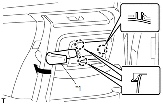
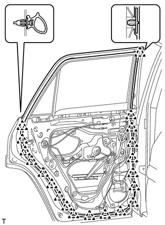
2. REMOVE REAR DOOR INSIDE HANDLE BEZEL LH
|
(a) Using moulding remover, detach the 3 claws to remove the rear door inside handle bezel LH as shown in the illustration. Text in Illustration
|
|
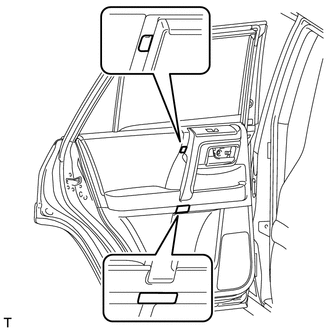
3. REMOVE REAR DOOR TRIM BOARD SUB-ASSEMBLY LH
|
(a) Detach the 4 claws to remove the 2 door armrest caps. |
|
|
(b) Remove the 3 screws. |
|
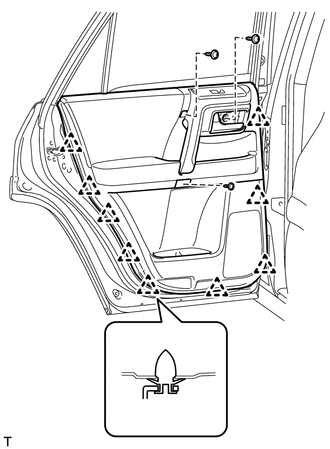
(c) Remove the 9 clips.
|
(d) Pull out the rear door trim board sub-assembly LH in the direction indicated by the arrow as shown in the illustration. |
|
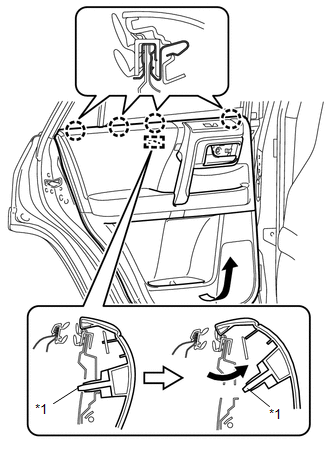
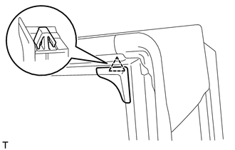
(e) Raise the rear door trim board sub-assembly LH and detach the 4 claws and reference boss to remove the rear door trim board sub-assembly LH together with the rear door inner glass weatherstrip LH.
Text in Illustration|
*1 |
Reference Boss |
|
(f) Disconnect the connector. |
|
|
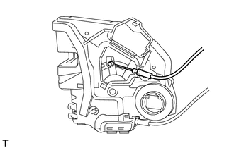
(g) Disconnect the rear door lock remote control cable assembly LH and rear door inside locking cable assembly LH as shown in the illustration. |
|
|
(h) Using a screwdriver, detach the claw to remove the clamp. |
|
4. REMOVE REAR DOOR INNER GLASS WEATHERSTRIP LH
|
(a) Using a screwdriver, detach the 3 claws to remove the rear door inner glass weatherstrip LH from the rear door trim board sub-assembly LH as shown in the illustration. |
|

5. REMOVE REAR POWER WINDOW REGULATOR SWITCH ASSEMBLY
6. REMOVE COURTESY LIGHT ASSEMBLY
7. REMOVE NO. 1 INTERIOR ILLUMINATION LIGHT ASSEMBLY (w/ Intuitive Parking Assist System)
8. REMOVE REAR SPEAKER ASSEMBLY
9. REMOVE REAR DOOR SERVICE HOLE COVER LH
|
(a) Disconnect the connector |
|
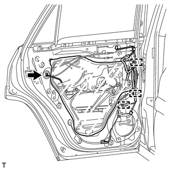
(b) Detach the 3 clamps, move the rear door wire out of the way to remove the rear door service hole cover LH.
HINT:
Remove any remaining butyl tape from the rear door panel.
10. REMOVE REAR DOOR FRAME GARNISH LH
|
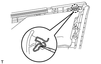
(a) Detach the clip to remove the rear door frame garnish LH. |
|
11. REMOVE REAR DOOR GLASS RUN LH
|
(a) Remove the rear door glass run LH. |
|
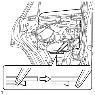
12. REMOVE REAR DOOR WINDOW REAR LOWER FRAME SUB-ASSEMBLY LH
|
(a) Loosen the temporary bolt. Text in Illustration
|
|
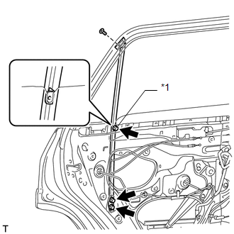
(b) Remove the 2 bolts and screw.
(c) Remove the rear door window rear lower frame sub-assembly LH.
NOTICE:
When the rear door window rear lower frame sub-assembly LH is removed, do not allow the rear door quarter window glass LH to fall.
(d) Remove the temporary bolt from the rear door window rear lower frame sub-assembly LH.
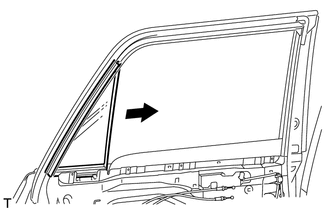
13. REMOVE REAR DOOR QUARTER WINDOW GLASS LH
|
(a) Remove the rear door quarter window glass LH and rear door quarter window weatherstrip LH as a unit as shown in the illustration. |
|
14. REMOVE REAR DOOR QUARTER WINDOW WEATHERSTRIP LH
(a) Remove the rear door quarter window weatherstrip LH from the rear door quarter window glass LH.
15. REMOVE REAR DOOR GLASS SUB-ASSEMBLY LH
(a) Connect the rear power window regulator switch assembly.
(b) Connect the cable to the negative (-) battery terminal.
(c) Move the arm of the rear door window regulator sub-assembly LH so that the roller on the arm can be seen through the service hole.
(d) Disconnect the cable from the negative (-) battery terminal.
NOTICE:
When disconnecting the cable, some systems need to be initialized after the cable
is reconnected (See page ).
(e) Disconnect the rear power window regulator switch assembly.
|
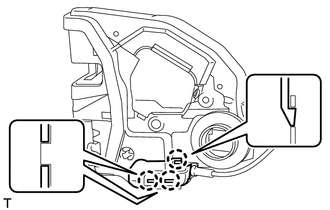
(f) Remove the rear door glass sub-assembly LH from the rear door window regulator sub-assembly LH as shown in the illustration. |
|
|
(g) Remove the rear door glass sub-assembly LH as indicated by the arrows in the order shown in the illustration. NOTICE: Do not damage the rear door glass sub-assembly LH. |
|

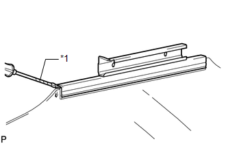
16. REMOVE REAR DOOR GLASS CHANNEL SUB-ASSEMBLY LH
|
(a) Using a screwdriver, remove the rear door glass channel sub-assembly LH. Text in Illustration
HINT: Tape the screwdriver tip before use. |
|
17. REMOVE REAR DOOR GLASS CHANNEL FILLER
(a) Remove the rear door glass channel filler.
18. REMOVE REAR DOOR WINDOW REGULATOR SUB-ASSEMBLY LH
|
(a) Disconnect the connector. |
|
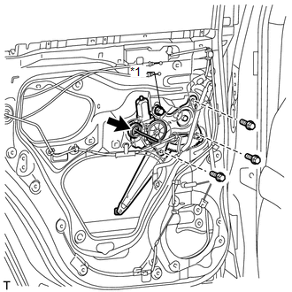
(b) Loosen the temporary bolt.
Text in Illustration|
*1 |
Temporary Bolt |
NOTICE:
Do not remove the temporary bolt. If the temporary bolt is removed, the rear door window regulator sub-assembly LH may fall and cause damage.
(c) Remove the 3 bolts.
(d) Remove the rear door window regulator sub-assembly LH.
(e) Remove the temporary bolt from the rear door window regulator sub-assembly LH.
19. REMOVE REAR POWER WINDOW REGULATOR MOTOR ASSEMBLY LH
20. REMOVE REAR DOOR LOCK ASSEMBLY LH
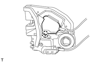
21. REMOVE REAR DOOR LOCK REMOTE CONTROL CABLE ASSEMBLY LH
|
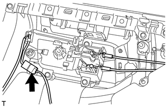
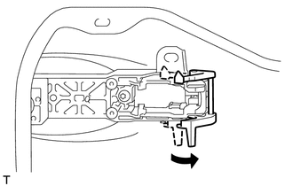
(a) Using a screwdriver, detach the claw to open the cover. HINT: Tape the screwdriver tip before use. |
|
|
(b) Remove the rear door lock remote control cable assembly LH from the rear door lock assembly LH. |
|
22. REMOVE REAR DOOR INSIDE LOCKING CABLE ASSEMBLY LH
|
(a) Using a screwdriver, detach the 3 claws to open the cover. HINT: Tape the screwdriver tip before use. |
|
|
(b) Remove the rear door inside locking cable assembly LH from the rear door lock assembly LH. |
|

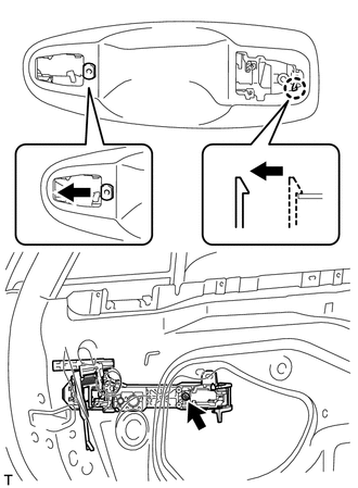
23. REMOVE REAR DOOR OUTSIDE HANDLE COVER LH
|
(a) Using a T30 "TORX" socket wrench, loosen the screw. HINT: The screw cannot be removed because it is integrated into the rear door outside handle frame sub-assembly LH. |
|
(b) Detach the claw to remove the rear door outside handle cover LH.
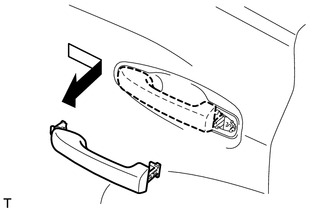
24. REMOVE REAR DOOR OUTSIDE HANDLE ASSEMBLY LH
|
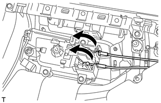
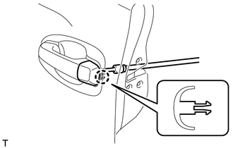
(a) Move the lever in the direction indicated by the arrow in the illustration. |
|
|
(b) Remove the rear door outside handle assembly LH as shown in the illustration. |
|
25. REMOVE REAR DOOR FRONT OUTSIDE HANDLE PAD
|
(a) Detach the 3 claws to remove the rear door front outside handle pad. |
|
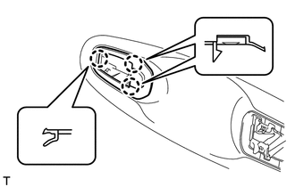
26. REMOVE REAR DOOR REAR OUTSIDE HANDLE PAD
|
(a) Detach the 2 claws to remove the rear door rear outside handle pad. |
|
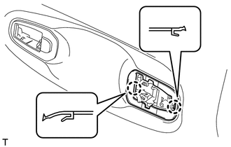
27. REMOVE REAR DOOR OUTSIDE HANDLE FRAME SUB-ASSEMBLY LH
|
(a) Using a T30 "TORX" socket wrench, loosen the screw. |
|
(b) Slide the rear door outside handle frame sub-assembly LH to detach the door handle nut and claw of the rear door outside handle frame sub-assembly LH. Then remove the rear door outside handle frame sub-assembly LH.
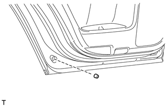
28. REMOVE REAR DOOR CHECK ASSEMBLY LH
|
(a) Remove the bolt, 2 nuts and rear door check assembly LH. |
|

29. REMOVE REAR DOOR WEATHERSTRIP LH
|
(a) Using a clip remover, detach the 20 clips to remove the rear door weatherstrip LH. |
|
30. REMOVE REAR DOOR PANEL CUSHION
|
(a) Using a clip remover, detach the claw to remove the rear door panel cushion. |
|
31. REMOVE REAR DOOR BELT MOULDING LH
32. REMOVE REAR DOOR FRONT WINDOW FRAME MOULDING LH
33. REMOVE NO. 2 BLACK OUT TAPE LH
34. REMOVE REAR DOOR LOWER OUTSIDE STRIPE LH
35. REMOVE REAR DOOR OUTSIDE STRIPE LH
36. REMOVE REAR DOOR OUTSIDE MOULDING LH
37. REMOVE REAR DOOR OUTSIDE MOULDING LH (w/ Intuitive Parking Assist System)
38. REMOVE NO. 3 OUTSIDE MOULDING RETAINER
 Components
COMPONENTS
ILLUSTRATION
ILLUSTRATION
ILLUSTRATION
ILLUSTRATION
...
 Adjustment
ADJUSTMENT
CAUTION / NOTICE / HINT
HINT:
Centering bolts are used to mount the door hinge to the vehicle body
and door. The door cannot be adjusted with the centering bolts installed. ...
Other materials about Toyota 4Runner:
Removal
REMOVAL
PROCEDURE
1. REMOVE PARK/NEUTRAL POSITION SWITCH ASSEMBLY
(a) Disconnect the switch connector.
(b) Using a screwdriver, bend the tabs of the lock washer.
(c) Remove the lock nut and l ...
Lost Communication with Front Satellite Sensor Bus (B161A/8A)
DESCRIPTION
The front collision sensor circuit (front airbag sensor RH circuit and front
airbag sensor LH circuit) is composed of the center airbag sensor assembly, front
airbag sensor RH and front airbag sensor LH.
The front airbag sensor RH or front ai ...
0.0147