Toyota 4Runner: Amplifier Antenna
Components
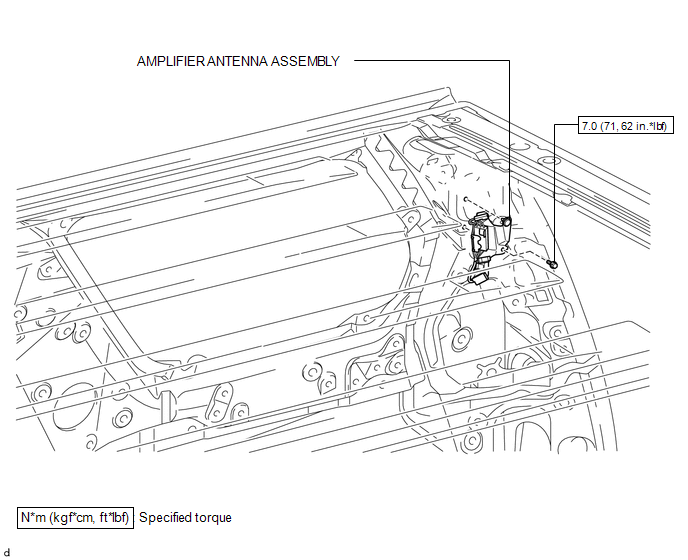
COMPONENTS
ILLUSTRATION
Removal
REMOVAL
PROCEDURE
1. REMOVE ROOF HEADLINING ASSEMBLY
(See page .gif) )
)
2. REMOVE AMPLIFIER ANTENNA ASSEMBLY
|
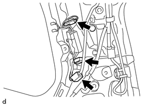
(a) Disconnect the 3 connectors. |
|
|
(b) Remove the clip. |
|
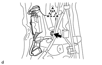
(c) Remove the bolt and amplifier antenna assembly.
Installation
INSTALLATION
PROCEDURE
1. INSTALL AMPLIFIER ANTENNA ASSEMBLY
(a) Install the amplifier antenna assembly with the bolt and clip.
Torque:
7.0 N·m {71 kgf·cm, 62 in·lbf}
(b) Connect the 3 connectors.
2. INSTALL ROOF HEADLINING ASSEMBLY
(See page .gif) )
)
 Audio / Video
...

Other materials about Toyota 4Runner:
Air Conditioning Control Panel does not Operate
DESCRIPTION
When a switch of the air conditioning control assembly is operated, the air conditioning
control assembly uses LIN communication to communicate with the air conditioning
amplifier. If a switch of the air conditioning control assembly does not ...
AV Signal Stoppage (Low Battery Voltage) (B158F)
DESCRIPTION
This DTC is stored when a video or audio signal is interrupted due to battery
voltage input to the radio and display receiver assembly dropping temporarily.
DTC No.
Detection Item
DTC Detection Condition
...
0.0098