Toyota 4Runner: Center Airbag Sensor Assembly Communication Circuit Malfunction (B1790)
DESCRIPTION
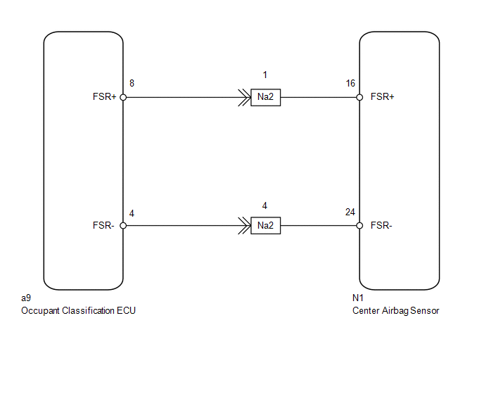
The center airbag sensor communication circuit consists of the occupant classification ECU and center airbag sensor.
DTC B1790 is stored when a malfunction is detected in the center airbag sensor communication circuit.
|
DTC Code |
DTC Detection Condition |
Trouble Area |
|---|---|---|
|
B1790 |
One of the following conditions is met:
|
|
HINT:
- When DTC B1630/32 is stored as a result of troubleshooting the airbag system, perform troubleshooting for DTC B1790 of the occupant classification system.
- Use the Techstream to check for DTCs of the occupant classification ECU, otherwise the DTCs cannot be read.
WIRING DIAGRAM
CAUTION / NOTICE / HINT
HINT:
- If troubleshooting (wire harness inspection) is difficult to perform, remove the front RH seat installation bolts to see the undersurface of the seat cushion.
- In the above case, hold the seat so that it does not fall down. Holding the seat for a long period of time may cause problems, such as seat rail deformation. Hold the seat up only for as long as necessary.
PROCEDURE
|
1. |
CHECK FOR DTC |
(a) Turn the ignition switch to ON, and wait for at least 60 seconds.
(b) Clear the DTCs stored in memory (See page .gif)
).
HINT:
- First clear the DTCs stored in the occupant classification ECU, and then clear the DTCs stored in the center airbag sensor.
- Use the Techstream to clear the DTCs of the occupant classification ECU, otherwise the DTCs cannot be cleared.
(c) Turn the ignition switch off.
(d) Turn the ignition switch to ON, and wait for at least 60 seconds.
(e) Using the Techstream, check for DTCs of the occupant classification ECU (See
page ).
OK:
DTC B1790 is not output.
HINT:
DTCs other than DTC B1790 may be output at this time, but they are not related to this check.
| OK | .gif) |
USE SIMULATION METHOD TO CHECK |
|
.gif)
|
2. |
CHECK CONNECTION OF CONNECTOR |
(a) Turn the ignition switch off.
(b) Disconnect the cable from the negative (-) battery terminal, and wait for at least 90 seconds.
(c) Check that the connectors are properly connected to the occupant classification ECU and center airbag sensor.
OK:
Connectors are properly connected.
| NG | |
CONNECT CONNECTOR |
|
|
3. |
CHECK CONNECTOR |
(a) Disconnect the connectors from the center airbag sensor and occupant classification ECU.
(b) Check that the connectors (on the center airbag sensor side and occupant
classification ECU side) are not damaged (See page
).
OK:
Connectors are not deformed or damaged.
| NG | |
REPLACE HARNESS OR CONNECTOR |
|
|
4. |
CHECK OCCUPANT CLASSIFICATION SYSTEM CIRCUIT |
|
(a) Connect the cable to the negative (-) battery terminal, and wait for at least 2 seconds. |
|
(b) Measure the voltage according to the value(s) in the table below.
Standard Voltage:
|
Tester Connection |
Switch Condition |
Specified Condition |
|---|---|---|
|
a9-8 (FSR+) - Body ground |
Ignition switch ON |
Below 1 V |
|
a9-4 (FSR-) - Body ground |
(c) Turn the ignition switch off.
(d) Disconnect the cable from the negative (-) battery terminal, and wait for at least 90 seconds.
(e) Using a service wire, connect terminals 16 (FSR+) and 24 (FSR-) of connector B.
NOTICE:
Do not forcibly insert the service wire into the terminals of the connector.
(f) Measure the resistance according to the value(s) in the table below.
Standard Resistance:
|
Tester Connection |
Condition |
Specified Condition |
|---|---|---|
|
a9-8 (FSR+) - a9-4 (FSR-) |
Always |
Below 1 Ω |
(g) Disconnect the service wire from connector B.
(h) Measure the resistance according to the value(s) in the table below.
Standard Resistance:
|
Tester Connection |
Condition |
Specified Condition |
|---|---|---|
|
a9-8 (FSR+) - a9-4 (FSR-) |
Always |
1 MΩ or higher |
|
a9-8 (FSR+) - Body ground |
||
|
a9-4 (FSR-) - Body ground |
|
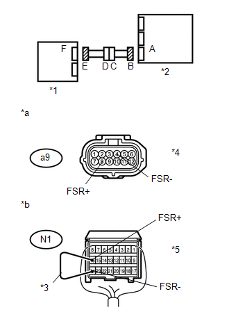
*1 |
Occupant Classification ECU |
|
*2 |
Center Airbag Sensor |
|
*3 |
Service Wire |
|
*4 |
Connector E |
|
*5 |
Connector B |
|
*a |
Front view of wire harness connector (to Occupant Classification ECU) |
|
*b |
Front view of wire harness connector (to Center Airbag Sensor) |
| NG | |
GO TO STEP 10 |
|
|
5. |
CHECK FOR DTC |
(a) Connect the connectors to the occupant classification ECU and center airbag sensor.
(b) Connect the cable to the negative (-) battery terminal, and wait for at least 2 seconds.
(c) Turn the ignition switch to ON, and wait for at least 60 seconds.
(d) Clear the DTCs stored in memory (See page
).
HINT:
- First clear the DTCs stored in the occupant classification ECU, and then clear the DTCs stored in the center airbag sensor.
- Use the Techstream to clear the DTCs of the occupant classification ECU, otherwise the DTCs cannot be cleared.
(e) Turn the ignition switch off.
(f) Turn the ignition switch to ON, and wait for at least 60 seconds.
(g) Using the Techstream, check for DTCs of the occupant classification ECU (See
page ).
OK:
DTC B1790 is not output.
HINT:
DTCs other than DTC B1790 may be output at this time, but they are not related to this check.
| OK | |
USE SIMULATION METHOD TO CHECK |
|
|
6. |
REPLACE OCCUPANT CLASSIFICATION ECU |
(a) Turn the ignition switch off.
(b) Disconnect the cable from the negative (-) battery terminal, and wait for at least 90 seconds.
(c) Replace the occupant classification ECU (See page
).
HINT:
Perform the inspection using parts from a normal vehicle when possible.
|
|
7. |
PERFORM ZERO POINT CALIBRATION |
(a) Connect the cable to the negative (-) battery terminal, and wait for at least 2 seconds.
(b) Turn the ignition switch to ON, and wait for at least 60 seconds.
(c) Using the Techstream, perform the zero point calibration (See page
).
OK:
"Zero Point Calibration is complete." is displayed.
|
|
8. |
PERFORM SENSITIVITY CHECK |
(a) Using the Techstream, perform the sensitivity check (See page
).
Standard range:
27 to 33 kg (59.5 to 72.8 lb)
|
|
9. |
CHECK FOR DTC |
(a) Clear the DTCs stored in memory (See page
).
HINT:
- First clear the DTCs stored in the occupant classification ECU, and then clear the DTCs stored in the center airbag sensor.
- Use the Techstream to clear the DTCs of the occupant classification ECU, otherwise the DTCs cannot be cleared.
(b) Turn the ignition switch off.
(c) Turn the ignition switch to ON, and wait for at least 60 seconds.
(d) Using the Techstream, check for DTCs of the occupant classification ECU (See
page ).
OK:
DTC B1790 is not output.
HINT:
DTCs other than DTC B1790 may be output at this time, but they are not related to this check.
| OK | |
END |
| NG | |
REPLACE CENTER AIRBAG SENSOR ASSEMBLY |
|
10. |
CHECK FRONT SEAT WIRE RH |
|
(a) Disconnect the front seat wire RH connector from the floor wire. |
|
(b) Connect the cable to the negative (-) battery terminal, and wait for at least 2 seconds.
(c) Measure the voltage according to the value(s) in the table below.
Standard Voltage:
|
Tester Connection |
Switch Condition |
Specified Condition |
|---|---|---|
|
Na2-1 (FSR+) - Body ground |
Ignition switch ON |
Below 1 V |
|
Na2-4 (FSR-) - Body ground |
(d) Turn the ignition switch off.
(e) Disconnect the connector from the occupant classification ECU.
(f) Using a service wire, connect terminals 8 (FSR+) and 4 (FSR-) of connector E.
NOTICE:
Do not forcibly insert the service wire into the terminals of the connector.
(g) Measure the resistance according to the value(s) in the table below.
Standard Resistance:
|
Tester Connection |
Condition |
Specified Condition |
|---|---|---|
|
Na2-1 (FSR+) - Na2-4 (FSR-) |
Always |
Below 1 Ω |
(h) Disconnect the service wire from connector E.
(i) Measure the resistance according to the value(s) in the table below.
Standard Resistance:
|
Tester Connection |
Condition |
Specified Condition |
|---|---|---|
|
Na2-1 (FSR+) - Na2-4 (FSR-) |
Always |
1 MΩ or higher |
|
Na2-1 (FSR+) - Body ground |
||
|
Na2-4 (FSR-) - Body ground |
|
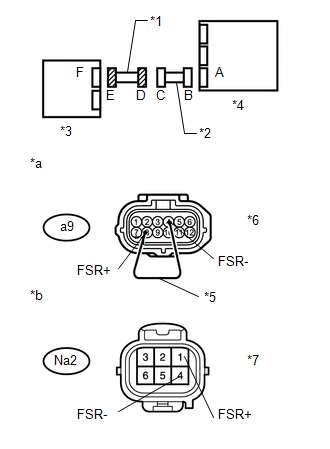
*1 |
Front Seat Wire RH |
|
*2 |
Floor Wire |
|
*3 |
Occupant Classification ECU |
|
*4 |
Center Airbag Sensor |
|
*5 |
Service Wire |
|
*6 |
Connector E |
|
*7 |
Connector D |
|
*a |
Front view of wire harness connector (to Occupant Classification ECU) |
|
*b |
Front view of wire harness connector (to Front Seat Wire RH) |
| OK | |
REPLACE FLOOR WIRE |
| NG | |
REPLACE FRONT SEAT WIRE RH |
 Rear Occupant Classification Sensor RH Collision Detection (B1788)
DESCRIPTION
DTC B1788 is stored when the occupant classification ECU receives a collision
detection signal, which is sent by the occupant classification sensor rear RH when
an accident occurs.
D ...
 Rear Occupant Classification Sensor LH Collision Detection (B1787)
DESCRIPTION
DTC B1787 is stored when the occupant classification ECU receives a collision
detection signal, which is sent by the rear occupant classification sensor LH when
an accident occurs.
D ...
Other materials about Toyota 4Runner:
If the engine will not start
If the engine will not start even though correct starting procedures are
being followed (, 173), consider each of the following points:
The engine will not start even though the starter motor operates normally.
One of the following may be the cause of the ...
Engine (ignition) switch (vehicles without a smart key system)
Starting the engine
Check that the parking brake is
set.
Check that the shift lever is
set in P.
Firmly depress the brake pedal.
Turn the engine switch to the
“START” position to start the engine.
Changing the engine switch positions
1. � ...
0.0208