Toyota 4Runner: Clearance Sonar Main Switch
Components
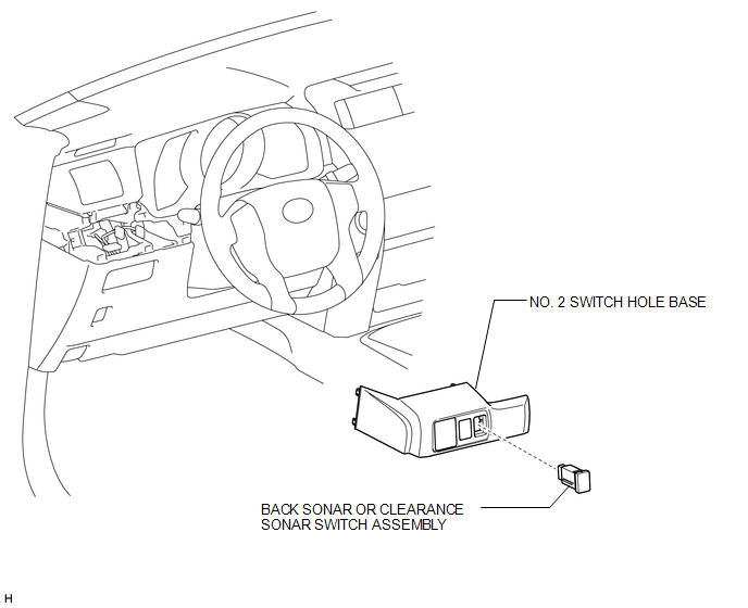
COMPONENTS
ILLUSTRATION
Removal
REMOVAL
PROCEDURE
1. REMOVE NO. 2 SWITCH HOLE BASE
.gif)
2. REMOVE BACK SONAR OR CLEARANCE SONAR SWITCH ASSEMBLY
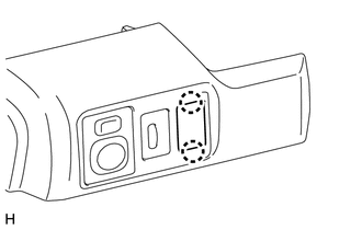
(a) Detach the 2 claws and remove the back sonar or clearance sonar switch.
Inspection
INSPECTION
PROCEDURE
1. INSPECT BACK SONAR OR CLEARANCE SONAR SWITCH ASSEMBLY
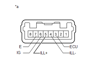
(a) Check the resistance.
(1) Measure the resistance according to the value(s) in the table below.
Standard Resistance:
|
Tester Connection |
Switch Condition |
Specified Condition |
|---|---|---|
|
3 (ECU) - 6 (IG) |
Sonar switch off |
10 kΩ or higher |
|
Sonar switch on |
Below 1 Ω |
If the result is not as specified, replace the back sonar or clearance sonar switch assembly.
(b) Apply battery voltage to the connector and check the LED illumination condition.
OK:
|
Measurement Condition |
Specified Condition |
|---|---|
|
Battery positive (+) → Terminal 3 (ECU) Battery negative (-) → Terminal 7 (E) |
LED illuminates |
|
Battery positive (+) → Terminal 5 (ILL+) Battery negative (-) → Terminal 4 (ILL-) |
LED illuminates |
If the result is not as specified, replace the back sonar or clearance sonar switch assembly.
Text in Illustration|
*a |
Component without harness connected (Back Sonar or Clearance Sonar Switch Assembly) |
Installation
INSTALLATION
PROCEDURE
1. INSTALL BACK SONAR OR CLEARANCE SONAR SWITCH ASSEMBLY
(a) Attach the 2 claws to install the back sonar or clearance sonar switch.
2. INSTALL NO. 2 SWITCH HOLE BASE
.gif)

 Clearance Warning Buzzer
Components
COMPONENTS
ILLUSTRATION
Removal
REMOVAL
PROCEDURE
1. REMOVE INSTRUMENT PANEL SUB-ASSEMBLY
(a) Remove the instrument panel sub-assembly (See page
).
2. REMOVE NO. 1 CLEARANCE ...
Other materials about Toyota 4Runner:
Disassembly
DISASSEMBLY
PROCEDURE
1. REMOVE FRONT NO. 2 AXLE INBOARD JOINT BOOT CLAMP
(a) Hold the drive shaft lightly in a vise between aluminum plates.
(b) Using pliers, remove the front No. 2 axle inboard joint boot clamp
as shown in the illustration ...
Sensor (Motor) Failure (B2341,B2344)
DESCRIPTION
When the sliding roof drive gear sub-assembly detects a motor malfunction
and the sliding roof operation is stopped, DTC B2341 is stored.
When the sliding roof drive gear sub-assembly detects a gear position
malfunctio ...
0.0073