Toyota 4Runner: Clearance Warning Buzzer
Components
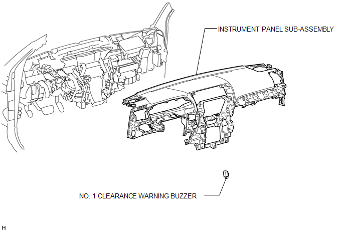
COMPONENTS
ILLUSTRATION
Removal
REMOVAL
PROCEDURE
1. REMOVE INSTRUMENT PANEL SUB-ASSEMBLY
(a) Remove the instrument panel sub-assembly (See page
.gif) ).
).
2. REMOVE NO. 1 CLEARANCE WARNING BUZZER
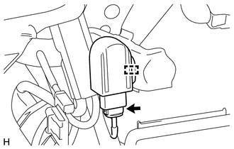
(a) Disconnect the connector.
(b) Detach the clamp and remove the No. 1 clearance warning buzzer.
Installation
INSTALLATION
PROCEDURE
1. INSTALL NO. 1 CLEARANCE WARNING BUZZER
(a) Attach the clamp to install the No. 1 clearance warning buzzer.
(b) Connect the connector.
2. INSTALL INSTRUMENT PANEL SUB-ASSEMBLY
(a) Install the instrument panel sub-assembly (See page
.gif) ).
).
 Clearance Sonar Main Switch
Components
COMPONENTS
ILLUSTRATION
Removal
REMOVAL
PROCEDURE
1. REMOVE NO. 2 SWITCH HOLE BASE
2. REMOVE BACK SONAR OR CLEARANCE SONAR SWITCH ASSEMBLY
(a) Detach the 2 claws and remo ...
 Clearance Warning Ecu
Components
COMPONENTS
ILLUSTRATION
Removal
REMOVAL
PROCEDURE
1. DISCONNECT CABLE FROM NEGATIVE BATTERY TERMINAL
CAUTION:
Wait at least 90 seconds after disconnecting the cable from the n ...
Other materials about Toyota 4Runner:
Image from Camera for Rear View Monitor is Abnormal
DESCRIPTION
The display signal from the rear television camera assembly transmits to the
radio and display receiver assembly.
WIRING DIAGRAM
PROCEDURE
1.
CHECK HARNESS AND CONNECTOR (RADIO AND DISPLAY RECEIVER ASSEMBLY - REAR
...
XM® Satellite Radio (if equipped)
Receiving XM® Satellite Radio
Press
or
.
The display changes as follows each time
or
is pressed.
Type A: AM → SAT1 → SAT2 → SAT3 Type B and C: AM → FM → SAT
Turn
or
to select the desired channel in all
the categories or press “� ...
0.0078