Toyota 4Runner: Diagnosis Circuit
DESCRIPTION
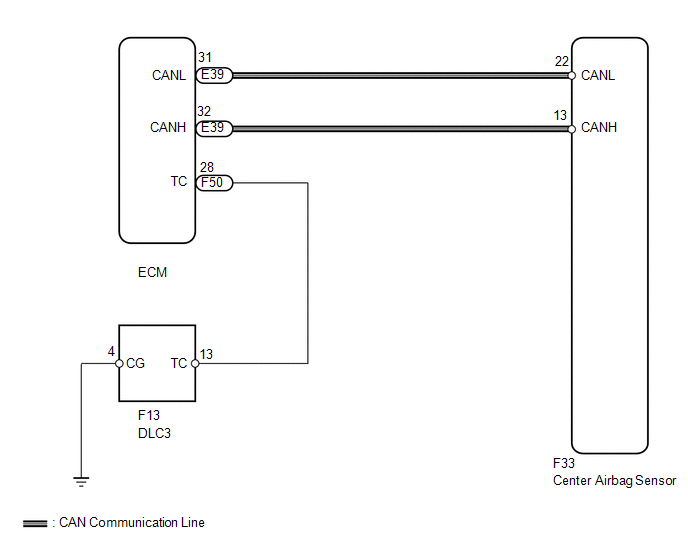
DTC output mode is set by connecting terminals TC and CG of the DLC3.
DTCs are output by the blinking of the SRS warning light.
HINT:
- When each warning light continues blinking, a ground short in the wiring of terminal TC of the DLC3 or an internal ground short in each ECU is suspected.
- A DTC output mode signal is transmitted through the CAN communication system to each ECU including the center airbag sensor. Thus, when all systems do not enter DTC output mode, there may be an ECM malfunction.
WIRING DIAGRAM
CAUTION / NOTICE / HINT
NOTICE:
When disconnecting the cable from the negative (-) battery terminal while performing
repairs, some systems need to be initialized after the cable is reconnected (See
page .gif) ).
).
PROCEDURE
|
1. |
CHECK CAN COMMUNICATION SYSTEM |
(a) Check if a CAN communication system DTC is output (See page
).
Result
|
Result |
Proceed to |
|---|---|
|
DTC is not output |
A |
|
DTC is output |
B |
| B | .gif) |
REPAIR CIRCUITS INDICATED BY OUTPUT DTCS |
|
.gif)
|
2. |
CHECK HARNESS AND CONNECTOR (DLC3 - ECM) |
|
(a) Turn the ignition switch off. |
|
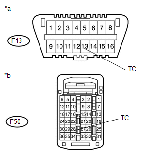
(b) Disconnect the F50 connector from the ECM.
(c) Measure the resistance according to the value(s) in the table below.
Standard Resistance:
|
Tester Connection |
Condition |
Specified Condition |
|---|---|---|
|
F13-13 (TC) - F50-28 (TC) |
Always |
Below 1 Ω |
|
*a |
Front view of DLC3 |
|
*b |
Rear view of wire harness connector (to ECM) |
| NG | |
REPAIR OR REPLACE HARNESS OR CONNECTOR |
|
|
3. |
CHECK HARNESS AND CONNECTOR (DLC3 - BODY GROUND) |
|
(a) Measure the resistance according to the value(s) in the table below. Standard Resistance:
|
|
| NG | |
REPAIR OR REPLACE HARNESS OR CONNECTOR |
|
|
4. |
CHECK HARNESS AND CONNECTOR (ECM - BODY GROUND) |
|
(a) Measure the resistance according to the value(s) in the table below. Standard Resistance:
|
|
| OK | |
REPLACE CENTER AIRBAG SENSOR ASSEMBLY |
| NG | |
REPAIR OR REPLACE HARNESS OR CONNECTOR OR EACH ECU |
 SRS Warning Light does not Come ON
DESCRIPTION
Refer to "SRS Warning Light Remains ON" (See page
).
WIRING DIAGRAM
Refer to "SRS Warning Light Remains ON" (See page
).
CAUTION / NOTICE / HINT
NOTICE:
When ...
 Center Airbag Sensor Assembly
Components
COMPONENTS
ILLUSTRATION
On-vehicle Inspection
ON-VEHICLE INSPECTION
PROCEDURE
1. CHECK AIRBAG SENSOR ASSEMBLY (VEHICLE NOT INVOLVED IN COLLISION)
(a) Perform a diagnostic syste ...
Other materials about Toyota 4Runner:
Door Side Airbag Sensor RH Malfunction (B1690/15,B1695/16)
DESCRIPTION
The side airbag sensor LH or RH consists of the safing sensor, diagnostic circuit,
lateral deceleration sensor, etc.
If the center airbag sensor receives signals from the lateral deceleration sensor,
it determines whether the SRS should be ac ...
Luggage compartment features
Cargo hooks
Vehicles with third seats
Fold down the third seats.
Raise the hook to use.
The cargo hooks are provided for securing loose items.
Vehicles without third seats
Raise the hook to use.
The cargo hooks are provided for securing loose items ...
0.01