Toyota 4Runner: Disassembly
DISASSEMBLY
PROCEDURE
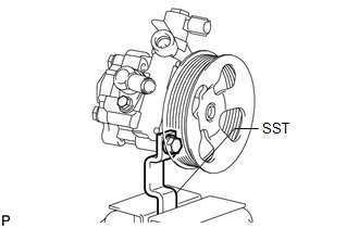
1. SECURE VANE PUMP ASSEMBLY
|
(a) Using SST, secure the vane pump in a vise. SST: 09630-00014 09631-00132 |
|
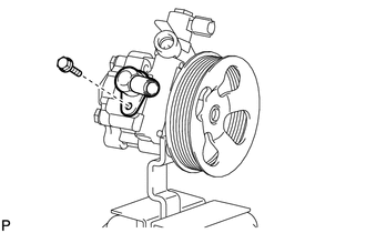
2. REMOVE SUCTION PORT UNION
|
(a) Remove the bolt and suction port union from the vane pump. |
|
(b) Using a screwdriver, remove the O-ring from the suction port union.
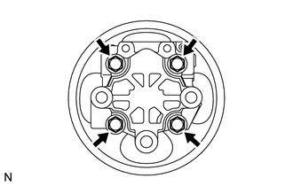
3. REMOVE VANE PUMP REAR HOUSING
|
(a) Remove the 4 bolts and vane pump rear housing from the vane pump front housing. |
|
|
(b) Using a screwdriver, remove the O-ring from the vane pump rear housing. |
|
4. REMOVE VANE PUMP SHAFT WITH PULLEY
|
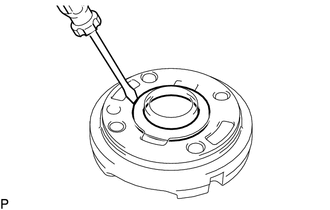
(a) Using 2 screwdrivers, remove the snap ring from the vane pump shaft. |
|
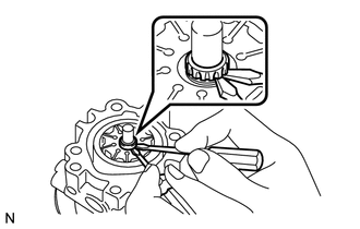
(b) Remove the vane pump shaft with pulley.
NOTICE:
Be careful not to drop or damage the vane pump shaft with vane pump pulley.
If it is damaged, replace the vane pump assembly.
5. REMOVE VANE PUMP ROTOR
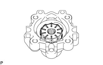
(a) Remove the 10 vane pump plates.
NOTICE:
Take care not to drop the vane pump plates.
(b) Remove the vane pump rotor from the vane pump front housing.
6. REMOVE VANE PUMP CAM RING
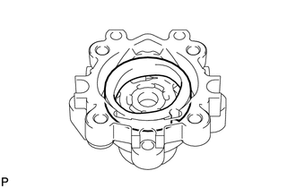
(a) Remove the cam ring from the vane pump front housing.
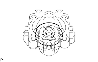
7. REMOVE VANE PUMP FRONT SIDE PLATE
|
(a) Remove the front side plate from the vane pump front housing. |
|
|
(b) Using a screwdriver, remove the O-ring from the front side plate. |
|
|
(c) Remove the O-ring from the vane pump front housing. |
|
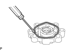
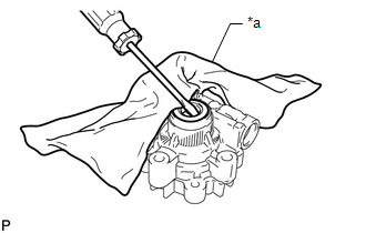
8. REMOVE VANE PUMP HOUSING OIL SEAL
|
(a) Using a screwdriver and piece of cloth, pry out the oil seal. Text in Illustration
NOTICE: Be careful not to damage the vane pump front housing. |
|
 Removal
REMOVAL
CAUTION / NOTICE / HINT
NOTICE:
When using a vise, do not overtighten it.
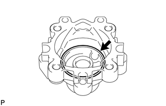
When installing the parts indicated by arrows, coat them with power
steering fluid (See page ).
...
 Inspection
INSPECTION
PROCEDURE
1. INSPECT VANE PUMP SHAFT AND BUSH IN VANE PUMP FRONT HOUSING
(a) Using a micrometer, measure the outer diameter of the vane pump shaft.
Text in Illustration
...
Other materials about Toyota 4Runner:
Loading CDs
Loading a CD (type A and B)
Insert a CD.
Loading a CD (type C)
Press
.
When the indicator on the slot turns
from amber to green, insert a CD.
Loading multiple CDs (type C only)
Press and hold
until you hear a beep.
When the indicator on th ...
Cellular Phone Registration Failure
PROCEDURE
1.
CHECK USAGE CONDITION
(a) Check that the vehicle and cellular phone meet the following conditions:
NOTICE:
If changing cellular phone settings, updating software, etc. is necessary, make
sure to obtain the per ...
0.0089