Toyota 4Runner: Removal
REMOVAL
CAUTION / NOTICE / HINT
NOTICE:
- When using a vise, do not overtighten it.
- When installing the parts indicated by arrows, coat them with power
steering fluid (See page
.gif) ).
).
PROCEDURE
1. DISCONNECT CABLE FROM NEGATIVE BATTERY TERMINAL
NOTICE:
When disconnecting the cable, some systems need to be initialized after the cable
is reconnected (See page ).
2. REMOVE FRONT WHEEL RH
3. REMOVE FRONT FENDER APRON SEAL RH
4. REMOVE V-BANK COVER SUB-ASSEMBLY
5. REMOVE AIR CLEANER CAP AND HOSE
6. REMOVE AIR CLEANER FILTER ELEMENT SUB-ASSEMBLY
7. REMOVE AIR CLEANER CASE
8. REMOVE FAN AND GENERATOR V BELT
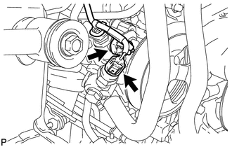
9. DISCONNECT POWER STEERING OIL PRESSURE SWITCH CONNECTOR
|
(a) Disconnect the 2 connectors. |
|
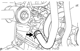
10. DISCONNECT NO. 1 OIL RESERVOIR TO PUMP HOSE
|
(a) Slide the clip and disconnect the oil reservoir to pump hose from the vane pump. |
|
11. DISCONNECT NO. 1 PRESSURE FEED TUBE
|
(a) Remove the union bolt and disconnect the pressure feed tube. |
|
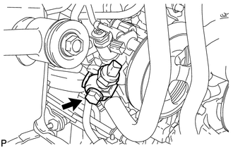
(b) Remove the gasket.
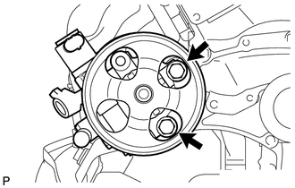
12. REMOVE VANE PUMP ASSEMBLY
|
(a) Remove the bolt and harness bracket. |
|
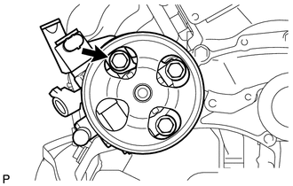
|
(b) Remove the 2 bolts and vane pump. |
|
 On-vehicle Inspection
ON-VEHICLE INSPECTION
PROCEDURE
1. INSPECT DRIVE BELT
(a) Visually check the belt for excessive wear, frayed cords, etc.
If any defect is found, replace the drive belt.
HINT:
Cracks on the rib s ...
 Disassembly
DISASSEMBLY
PROCEDURE
1. SECURE VANE PUMP ASSEMBLY
(a) Using SST, secure the vane pump in a vise.
SST: 09630-00014
09631-00132
2. RE ...
Other materials about Toyota 4Runner:
Inspection
INSPECTION
PROCEDURE
1. INSPECT PARK/NEUTRAL POSITION SWITCH ASSEMBLY
(a) Measure the resistance according to the value(s) in the table below.
Standard Resistance:
Tester Connection
Condition
Specified Condition
...
Illumination Circuit
DESCRIPTION
Power is supplied to the radio and display receiver assembly and steering pad
switch illumination when the light control switch is in the tail or head position.
WIRING DIAGRAM
CAUTION / NOTICE / HINT
NOTICE:
Inspect the fuses for c ...
0.0068