Toyota 4Runner: Disassembly
DISASSEMBLY
PROCEDURE
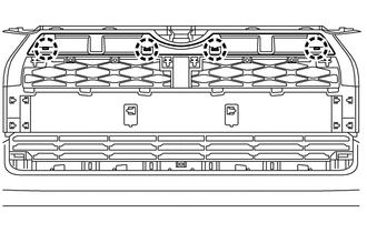
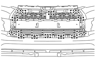
1. REMOVE RADIATOR GRILLE
.gif)
2. REMOVE NO. 2 ENGINE ROOM WIRE
(a) Disconnect each connector.
(b) Detach the 9 clamps to remove the No. 2 engine room wire.

3. REMOVE NO. 1 ULTRASONIC SENSOR
4. REMOVE ULTRASONIC SENSOR CLIP
5. REMOVE NO. 2 ULTRASONIC SENSOR RETAINER
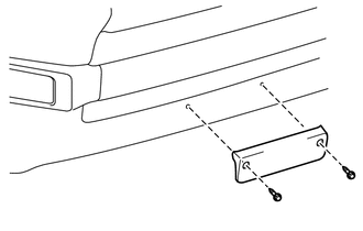
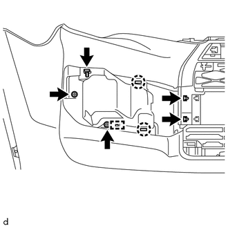
6. REMOVE FRONT BUMPER EXTENSION MOUNTING BRACKET (w/ License Plate Bracket)
|
(a) Remove the 2 screws and front bumper extension mounting bracket. |
|
7. REMOVE FRONT BUMPER SIDE MOULDING LH
|
(a) Remove the 2 outside moulding retainers. |
|
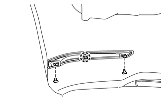
(b) Detach the claw to remove the front bumper side moulding LH.
8. REMOVE FRONT BUMPER SIDE MOULDING RH
HINT:
Use the same procedure as for the LH side.
9. REMOVE FRONT BUMPER LOWER SIDE SUPPORT LH
|
(a) Remove the 2 clips. |
|
(b) Detach the 5 claws to remove the front bumper lower side support LH.
10. REMOVE FRONT BUMPER LOWER SIDE SUPPORT RH
HINT:
Use the same procedure as for the LH side.
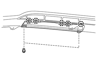
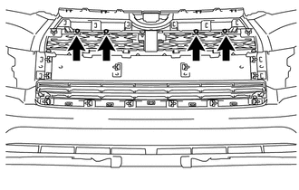
11. REMOVE NO. 2 RADIATOR GRILLE MOULDING
|
(a) Remove the 2 outside moulding retainers and 4 screws. |
|
|
(b) Detach the 4 claws to remove the No. 2 radiator grille moulding. |
|
12. REMOVE FRONT BUMPER SIDE MOULDING SUB-ASSEMBLY LH
|
(a) Remove the 3 outside moulding retainers. |
|
(b) Remove the 2 screws.
(c) Detach the 2 claws and guide to remove the front bumper side moulding sub-assembly LH.
13. REMOVE FRONT BUMPER SIDE MOULDING SUB-ASSEMBLY RH
HINT:
Use the same procedure as for the LH side.
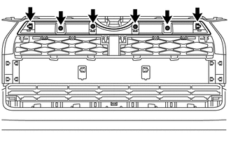
14. REMOVE FRONT BUMPER MOULDING SUB-ASSEMBLY
|
(a) Remove the 4 screws. |
|
|
(b) Remove the 15 outside moulding retainers. |
|
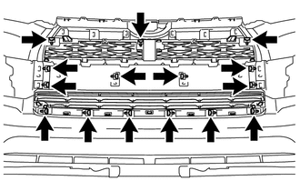
|
(c) Detach the 12 guides and 4 claws to remove the front bumper moulding sub-assembly. |
|
15. REMOVE FOG LIGHT ASSEMBLY LH
16. REMOVE FOG LIGHT ASSEMBLY RH
HINT:
Use the same procedure as for the LH side.
 Removal
REMOVAL
PROCEDURE
1. REMOVE UPPER RADIATOR SUPPORT SEAL
2. REMOVE FRONT BUMPER COVER
(a) Put protective tape around the front bumper cover.
(b) Remove the 3 bolts, 10 screws and 6 clips.
(c) ...
 Reassembly
REASSEMBLY
PROCEDURE
1. INSTALL FOG LIGHT ASSEMBLY LH
2. INSTALL FOG LIGHT ASSEMBLY RH
HINT:
Use the same procedure as for the LH side.
3. INSTALL FRONT BUMPER MOULDING SUB-ASSEMBLY
(a) Atta ...
Other materials about Toyota 4Runner:
Vehicle Control History
VEHICLE CONTROL HISTORY
1. Function Overview
(a) The vehicle control history is a function that records control data (record
data) when triggered by specific vehicle behavior. When DTCs are not detected according
to information provided by customers, by ...
Data Signal Circuit between Navigation Receiver Assembly and Stereo Jack Adapter
DESCRIPTION
The No. 1 stereo jack adapter assembly sends the sound data signal or image data
signal from a USB device to the navigation receiver assembly via this circuit.
WIRING DIAGRAM
PROCEDURE
1.
CHECK HARNESS AND CONNECTOR ( ...
0.0069