Toyota 4Runner: Disassembly
DISASSEMBLY
CAUTION / NOTICE / HINT
PROCEDURE
1. REMOVE FRONT WHEEL ADJUSTING NUT LH
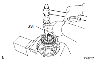
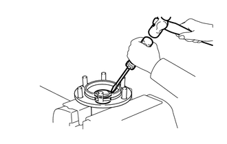
(a) Using SST and a hammer, unstake the adjusting nut.
SST: 09930-00010
|
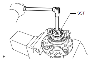
(b) Using SST, remove the adjusting nut. SST: 09318-12010 |
|
2. REMOVE FRONT AXLE WITH ABS ROTOR BEARING ASSEMBLY LH
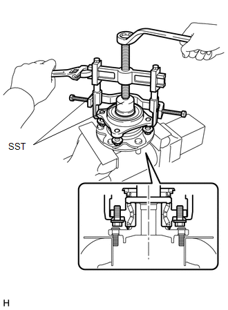
(a) Gently fix the front axle hub in a vise between aluminum plates.
NOTICE:
Do not damage the threads of the hub bolts.
|
(b) Using SST, remove the bearing. SST: 09710-30021 09710-03051 SST: 09950-40011 09951-04020 09952-04010 09953-04020 09954-04010 09955-04061 09957-04010 09958-04011 |
|
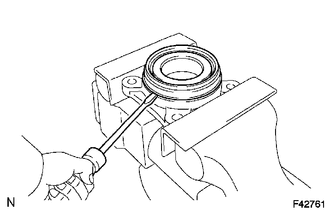
3. REMOVE FRONT AXLE HUB OIL SEAL LH
|
(a) Using a screwdriver, remove the front axle hub oil seal. |
|
4. REMOVE PLUG
|
(a) Using a screwdriver and hammer, remove the plug. |
|
 Removal
REMOVAL
CAUTION / NOTICE / HINT
HINT:
Use the same procedure for the RH and LH sides.
The procedure listed below is for the LH side.
PROCEDURE
1. REMOVE FRONT WHEEL
2. REMOVE D ...
 Reassembly
REASSEMBLY
CAUTION / NOTICE / HINT
PROCEDURE
1. INSTALL PLUG
(a) Using the SST and a hammer, install a new plug.
SST: 09950-60010
09951-00450
SST: 09950-70010
09951-07100
...
Other materials about Toyota 4Runner:
Replacement
REPLACEMENT
PROCEDURE
1. RECOVER REFRIGERANT FROM REFRIGERATION SYSTEM
(a) Start the engine.
(b) Turn the A/C switch on.
(c) Operate the cooler compressor while the engine speed is approximately 1000
rpm for 5 to 6 minutes to circulate the refrigerant a ...
Data List / Active Test
DATA LIST / ACTIVE TEST
1. DATA LIST
HINT:
Using the Techstream to read the Data List allows the values or states of switches,
sensors, actuators and other items to be read without removing any parts. This non-intrusive
inspection can be very useful bec ...
0.0244