Toyota 4Runner: Electrical Key Oscillator(for Front Floor)
Components
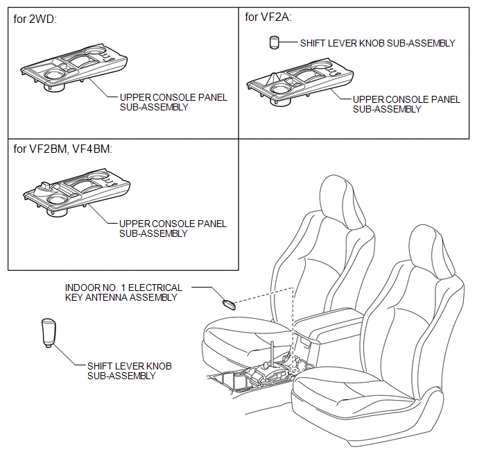
COMPONENTS
ILLUSTRATION
Installation
INSTALLATION
PROCEDURE
1. INSTALL INDOOR NO. 1 ELECTRICAL KEY ANTENNA ASSEMBLY
|
(a) Attach the clamp to install the indoor No. 1 electrical key antenna. |
|
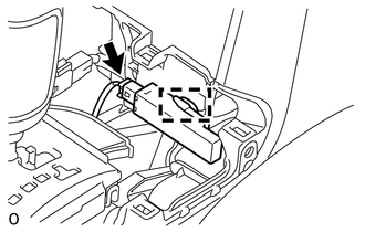
(b) Connect the connector.
2. INSTALL UPPER CONSOLE PANEL SUB-ASSEMBLY
.gif)
3. INSTALL SHIFT LEVER KNOB SUB-ASSEMBLY (for VF2A)
4. INSTALL SHIFT LEVER KNOB SUB-ASSEMBLY
Removal
REMOVAL
PROCEDURE
1. REMOVE SHIFT LEVER KNOB SUB-ASSEMBLY
.gif)
2. REMOVE SHIFT LEVER KNOB SUB-ASSEMBLY (for VF2A)
3. REMOVE UPPER CONSOLE PANEL SUB-ASSEMBLY
4. REMOVE INDOOR NO. 1 ELECTRICAL KEY ANTENNA ASSEMBLY
|
(a) Disconnect the connector. |
|
.png)
(b) Detach the clamp and remove the indoor No. 1 electrical key antenna.
 Removal
REMOVAL
PROCEDURE
1. DISCONNECT CABLE FROM NEGATIVE BATTERY TERMINAL
CAUTION:
Wait at least 90 seconds after disconnecting the cable from the negative (-)
battery terminal to disable the SRS sys ...

Other materials about Toyota 4Runner:
Back Door Support
Components
COMPONENTS
ILLUSTRATION
Removal
REMOVAL
PROCEDURE
1. REMOVE BACK DOOR DAMPER STAY SUB-ASSEMBLY LH
NOTICE:
Avoid touching the piston rod as much as possible to prevent foreign
matter from attaching to it. Be sure to hold the ...
Removal
REMOVAL
PROCEDURE
1. REMOVE SHIFT LEVER KNOB SUB-ASSEMBLY
2. REMOVE SHIFT LEVER KNOB SUB-ASSEMBLY (for VF2A)
3. REMOVE UPPER CONSOLE PANEL SUB-ASSEMBLY
4. REMOVE SEAT HEATER SWITCH
(a) Disconnect the 2 connectors.
...
0.0089