Toyota 4Runner: Removal
REMOVAL
PROCEDURE
1. REMOVE SHIFT LEVER KNOB SUB-ASSEMBLY
.gif)
2. REMOVE SHIFT LEVER KNOB SUB-ASSEMBLY (for VF2A)
3. REMOVE UPPER CONSOLE PANEL SUB-ASSEMBLY
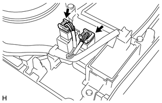
4. REMOVE SEAT HEATER SWITCH
|
(a) Disconnect the 2 connectors. |
|
|
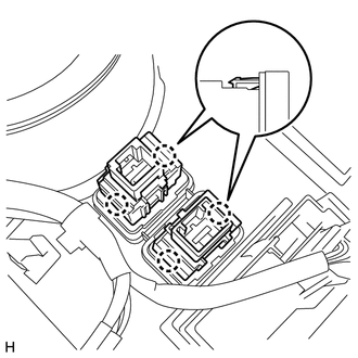
(b) Detach the 4 claws and remove the 2 switches. |
|
 Inspection
INSPECTION
PROCEDURE
1. INSPECT SEAT HEATER SWITCH LH
(a) Measure the resistance according to the value(s) in the table below.
Standard Resistance:
Tester Connection
Sw ...
 Installation
INSTALLATION
PROCEDURE
1. INSTALL SEAT HEATER SWITCH
(a) Attach the 4 claws to install the 2 switches.
(b) Connect the 2 connectors.
2. INSTALL UPPER CONSOLE PANEL SUB-ASSEMBLY
3. INSTALL SHI ...
Other materials about Toyota 4Runner:
Front Blower Motor
Components
COMPONENTS
ILLUSTRATION
Removal
REMOVAL
PROCEDURE
1. REMOVE NO. 2 INSTRUMENT PANEL UNDER COVER SUB-ASSEMBLY
2. REMOVE BLOWER WITH FAN MOTOR SUB-ASSEMBLY
(a) Detach the clamp.
(b) Disconnect the connector.
(c) Remove the ...
Short to Battery in Motor RH Circuit (25,26)
DESCRIPTION
When there is a short to battery in the side auto step motor circuit, the side
auto step controller ECU assembly will not operate the automatic running board.
DTC No.
Detection Condition
Trouble Area
...
0.0228