Toyota 4Runner: Engine does not Start
DESCRIPTION
The push-button start function uses a push-type engine switch, which the driver can operate by merely carrying the key. This system consists primarily of the power management control ECU, engine switch, ID code box, steering lock ECU, key, ACC relay, IG1 relay, IG2 relay and certification ECU. The power management control ECU controls the system. This function operates in cooperation with the smart key system.
WIRING DIAGRAM
- Refer to the SFI system (DTC P0617) (See page
.gif) ).
).
- Refer to DTC B2284 (See page ).
CAUTION / NOTICE / HINT
NOTICE:
- When using the Techstream with the engine switch off to troubleshoot: Connect the Techstream to the vehicle and turn a courtesy light switch on and off at 1.5 second intervals until communication between the Techstream and vehicle begins.
- Before performing the inspection, check that there are no problems related to the CAN communication system and LIN communication system.
- Inspect the fuses for circuits related to this system before performing the following inspection procedure.
HINT:
After the certification ECU, steering lock actuator assembly (steering lock ECU)
and/or ID code box is replaced, perform the registration procedure for the engine
immobiliser system (See page ).
PROCEDURE
|
1. |
CHECK IF ENGINE STARTS (INITIALIZE STEERING LOCK) |
(a) Place the key on the seat. Move the shift lever to P and depress the brake pedal.
(b) Check that the engine switch indicator is illuminated in green, push the engine switch, and check that the engine starts.
(c) Open and close the driver side door with the engine switch off.
(d) Check if the engine can be started.
OK:
Engine can be started.
HINT:
After the battery is discharged and then recharged, the engine may not start unless the steering lock is initialized using the above procedure.
| OK | .gif) |
USE SIMULATION METHOD TO CHECK |
|
.gif)
|
2. |
READ VALUE USING TECHSTREAM (POWER SUPPLY OPEN) AND CHECK FOR DTC |
(a) Read the value using the Techstream (Power Supply Open).
(1) Connect the Techstream to the DLC3.
(2) Turn the engine switch on (IG).
(3) Turn the Techstream on.
(4) Enter the following menus: Body Electrical / Smart Key / Data List.
(5) According to the display on the Techstream, read the Data List.
Smart Key|
Tester Display |
Measurement Item/Range |
Normal Condition |
Diagnostic Note |
|---|---|---|---|
|
Power Supply Open |
Power supply open / OK or NG (Past) |
OK: Power supply normal NG (Past): Power supply open occurred in past |
- |
(b) Check for DTCs.
(1) Enter the following menus: Body Electrical / (desired system) / Trouble Codes.
(2) Read the DTCs.
Result|
Result |
Proceed to |
|---|---|
|
No DTC is output, power supply open has not occurred in past |
A |
|
DTCs other than B2782 are output |
B |
|
Power supply open has occurred in past and/or DTC B2782 is output |
C |
| B | |
GO TO DTC CHART |
| C | |
GO TO STEERING LOCK SYSTEM (B2782) |
|
|
3. |
CHECK ENGINE SWITCH CONDITION |
(a) Check if the power source mode changes.
(1) When the key is inside the vehicle and the shift lever is in P, push the engine switch and check that the power source mode changes.
Result|
Result |
Proceed to |
|---|---|
|
OK: off → on (ACC) → on (IG) → off |
A |
|
Power source mode does not change to on (IG) or on (ACC). |
B |
|
Power source mode does not change to on (IG). |
C |
|
Power source mode does not change to on (ACC). |
D |
| B | |
GO TO POWER SOURCE MODE DOES NOT CHANGE TO ON (IG AND ACC) |
| C | |
GO TO POWER SOURCE MODE DOES NOT CHANGE TO ON (IG) |
| D | |
GO TO POWER SOURCE MODE DOES NOT CHANGE TO ON (ACC) |
|
|
4. |
CHECK CRANKING FUNCTION |
(a) Check the engine cranking function.
(1) When there is fuel in the fuel tank, the key is inside the vehicle and the shift lever is in P, check that depressing the brake pedal and pressing the engine switch cranks the engine.
OK:
Engine cranks.
| OK | |
GO TO SFI SYSTEM (HOW TO PROCEED WITH TROUBLESHOOTING) |
|
|
5. |
INSPECT PARK/NEUTRAL POSITION SWITCH |
|
(a) Disconnect the B42 park/neutral position switch connector. |
|
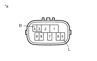
(b) Measure the resistance according to the value(s) in the table below.
Standard Resistance:
|
Tester Connection |
Condition |
Specified Condition |
|---|---|---|
|
4 (B) - 5 (L) |
Shift lever in P or N |
Below 1 Ω |
|
Shift lever not in P or N |
10 kΩ or higher |
|
*a |
Component without harness connected (Park/Neutral Position Switch) |
| NG | |
GO TO STEP 19 |
|
|
6. |
INSPECT ST RELAY |
|
(a) Remove the ST relay from the engine room relay block. |
|
.png)
(b) Measure the resistance according value(s) in the table below.
Standard Resistance:
|
Tester Connection |
Condition |
Specified Condition |
|---|---|---|
|
3 - 5 |
Battery voltage not applied to terminals 1 and 2 |
10 kΩ or higher |
|
Battery voltage applied to terminals 1 and 2 |
Below 1 Ω |
| NG | |
GO TO STEP 19 |
|
|
7. |
CHECK HARNESS AND CONNECTOR (POWER MANAGEMENT CONTROL ECU - BODY GROUND) |
(a) Disconnect the F81 power management control ECU connector.
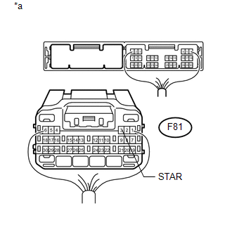
(b) Move the shift lever to P or N.
(c) Measure the resistance according to the value(s) in the table below.
Standard Resistance:
|
Tester Connection |
Condition |
Specified Condition |
|---|---|---|
|
F81-3 (STAR) - Body ground |
20°C (68°F) |
93.8 to 136.3 Ω |
|
*a |
Rear view of wire harness connector (to Power Management Control ECU) |
| NG | |
GO TO STEP 19 |
|
|
8. |
READ VALUE USING TECHSTREAM (STOP LIGHT SWITCH) |
(a) Connect the Techstream to the DLC3.
(b) Turn the engine switch on (IG).
(c) Turn the Techstream on.
(d) Enter the following menus: Body Electrical / Power Source Control / Data List.
(e) According to the display on the Techstream, read the Data List.
Power Source Control|
Tester Display |
Measurement Item/Range |
Normal Condition |
Diagnostic Note |
|---|---|---|---|
|
Stop Light Switch1 |
Stop light switch 1 / ON or OFF |
ON: Brake pedal depressed OFF: Brake pedal released |
- |
OK:
ON (brake pedal depressed) or OFF (brake pedal released) appears on the screen according to the condition of the brake pedal.
| NG | |
GO TO STEP 15 |
|
|
9. |
READ VALUE USING TECHSTREAM (STEERING UNLOCK SWITCH) |
(a) Connect the Techstream to the DLC3.
(b) Turn the engine switch on (IG).
(c) Turn the Techstream on.
(d) Enter the following menus: Body Electrical / Power Source Control / Data List.
(e) According to the display on the Techstream, read the Data List.
Power Source Control|
Tester Display |
Measurement Item/Range |
Normal Condition |
Diagnostic Note |
|---|---|---|---|
|
Steering Unlock Switch |
Steering unlock switch / ON or OFF |
ON: Steering lock released OFF: Steering lock locked |
- |
OK:
ON (steering lock released) or OFF (steering lock locked) appears on the screen according to the steering lock condition.
| NG | |
GO TO STEP 17 |
|
|
10. |
CHECK STEERING LOCK |
(a) Turn the engine switch from off to on (ACC) and check that the steering lock moves to the released position.
OK:
Lock moves to released position.
| NG | |
GO TO STEERING LOCK SYSTEM (HOW TO PROCEED WITH TROUBLESHOOTING) |
|
|
11. |
READ VALUE USING TECHSTREAM (ENGINE START REQUEST) |
(a) Connect the Techstream to the DLC3.
(b) Turn the Techstream on.
HINT:
When using the Techstream with the engine switch off, turn any of the door courtesy light switches on and off repeatedly at intervals of 1.5 seconds or less until communication between the tester and vehicle starts.
(c) Enter the following menus: Body Electrical / Smart Key / Data List.
(d) According to the display on the Techstream, read the Data List.
(e) Turn the engine switch on (IG).
Smart Key|
Tester Display |
Measurement Item/Range |
Normal Condition |
Diagnostic Note |
|---|---|---|---|
|
Engine Start Request |
Start request signal response / OK or NG |
OK: Received NG: Not received |
- |
OK:
OK appears on the screen.
| NG | |
REPLACE CERTIFICATION ECU |
|
|
12. |
READ VALUE USING TECHSTREAM (L CODE CHECK) |
(a) Connect the Techstream to the DLC3.
(b) Turn the Techstream on.
HINT:
When using the Techstream with the engine switch off, turn any of the door courtesy light switches on and off repeatedly at intervals of 1.5 seconds or less until communication between the tester and vehicle starts.
(c) Enter the following menus: Body Electrical / Smart Key / Data List.
(d) According to the display on the Techstream, read the Data List.
(e) Turn the engine switch on (IG).
Smart Key|
Tester Display |
Measurement Item/Range |
Normal Condition |
Diagnostic Note |
|---|---|---|---|
|
L Code Check |
L code certification result / OK or NG |
OK: L code certification result normal NG: L code certification result abnormal |
- |
OK:
OK (L code certification result normal) appears on the screen.
| NG | |
GO TO ENGINE IMMOBILISER SYSTEM (HOW TO PROCEED WITH TROUBLESHOOTING) |
|
|
13. |
READ VALUE USING TECHSTREAM (S CODE CHECK) |
(a) Connect the Techstream to the DLC3.
(b) Turn the Techstream on.
HINT:
When using the Techstream with the engine switch off, turn any of the door courtesy light switches on and off repeatedly at intervals of 1.5 seconds or less until communication between the tester and vehicle starts.
(c) Enter the following menus: Body Electrical / Smart Key / Data List.
(d) According to the display on the Techstream, read the Data List.
(e) Turn the engine switch on (IG).
Smart Key|
Tester Display |
Measurement Item/Range |
Normal Condition |
Diagnostic Note |
|---|---|---|---|
|
S Code Check |
S code certification result / OK or NG |
OK: S code certification result normal NG: S code certification result abnormal |
- |
OK:
OK (S code certification result normal) appears on the screen.
| NG | |
GO TO ENGINE IMMOBILISER SYSTEM (HOW TO PROCEED WITH TROUBLESHOOTING) |
|
|
14. |
READ VALUE USING TECHSTREAM (STARTER REQUEST SIGNAL) |
(a) Connect the Techstream to the DLC3.
(b) Turn the Techstream on.
HINT:
When using the Techstream with the engine switch off, turn any of the door courtesy light switches on and off repeatedly at intervals of 1.5 seconds or less until communication between the tester and vehicle starts.
(c) Enter the following menus: Body Electrical / Power Source Control / Data List.
(d) According to the display on the Techstream, read the Data List.
(e) Turn the engine switch on (IG).
Power Source Control|
Tester Display |
Measurement Item/Range |
Normal Condition |
Diagnostic Note |
|---|---|---|---|
|
Starter Request Signal |
Starter request signal monitor / ON or OFF |
ON: ST relay on OFF: ST relay off |
The engine switch is pressed and held with the shift lever in P or N. |
NOTICE:
Check that the engine switch indicator is illuminated in green and push the engine switch.
OK:
The Data List item changes from OFF to ON when the engine switch is pushed.
| OK | |
GO TO SFI SYSTEM (HOW TO PROCEED WITH TROUBLESHOOTING) |
| NG | |
REPLACE POWER MANAGEMENT CONTROL ECU |
|
15. |
INSPECT STOP LIGHT SWITCH ASSEMBLY |
(a) Inspect the stop light switch assembly (See page
).
| NG | |
REPLACE STOP LIGHT SWITCH ASSEMBLY |
|
|
16. |
CHECK HARNESS AND CONNECTOR (POWER MANAGEMENT CONTROL ECU - STOP LIGHT SWITCH ASSEMBLY) |
| OK | |
REPLACE POWER MANAGEMENT CONTROL ECU |
| NG | |
REPAIR OR REPLACE HARNESS OR CONNECTOR |
|
17. |
CHECK HARNESS AND CONNECTOR (POWER MANAGEMENT CONTROL ECU - STEERING LOCK ECU) |
| NG | |
REPAIR OR REPLACE HARNESS OR CONNECTOR |
|
|
18. |
INSPECT STEERING LOCK ACTUATOR ASSEMBLY (STEERING LOCK ECU) |
| OK | |
REPLACE POWER MANAGEMENT CONTROL ECU |
| NG | |
REPLACE STEERING LOCK ACTUATOR ASSEMBLY (STEERING LOCK ECU) |
|
19. |
REPAIR OR REPLACE HARNESS OR CONNECTOR, OR REPLACE ST RELAY, PARK/NEUTRAL POSITION SWITCH |
(a) Replace the ST relay, park/neutral position switch assembly with a new or normally functioning part, or repair or replace any damaged wire harness or connector.
|
|
20. |
READ VALUE USING TECHSTREAM (STARTER REQUEST SIGNAL) |
(a) Connect the Techstream to the DLC3.
(b) Turn the Techstream on.
HINT:
When using the Techstream with the engine switch off, turn any of the door courtesy light switches on and off repeatedly at intervals of 1.5 seconds or less until communication between the tester and vehicle starts.
(c) Enter the following menus: Body Electrical / Power Source Control / Data List.
(d) According to the display on the Techstream, read the Data List.
(e) Turn the engine switch on (IG).
Power Source Control|
Tester Display |
Measurement Item/Range |
Normal Condition |
Diagnostic Note |
|---|---|---|---|
|
Starter Request Signal |
Starter request signal monitor / ON or OFF |
ON: ST relay on OFF: ST relay off |
The engine switch is pressed and held with the shift lever in P or N. |
NOTICE:
Check that the engine switch indicator is illuminated in green and push the engine switch.
OK:
The Data List item changes from OFF to ON when the engine switch is pushed.
| NG | |
REPLACE POWER MANAGEMENT CONTROL ECU |
|
|
21. |
CHECK IF ENGINE STARTS |
(a) Place the key on the seat. Move the shift lever to P and depress the brake pedal.
(b) Check that the engine switch indicator is illuminated in green, push the engine switch and check that the engine starts.
(c) Open and close the driver side door with the engine switch off.
(d) Check if the engine can be started.
OK:
Engine can be started.
| OK | |
END |
| NG | |
GO TO SFI SYSTEM (HOW TO PROCEED WITH TROUBLESHOOTING) |
 Brake Signal Malfunction (B2284)
DESCRIPTION
This DTC is stored when the brake signal information from the cable and the brake
signal information from the CAN communication line are inconsistent
HINT:
When the power management c ...
 Power Source Mode does not Change to ON (IG and ACC)
DESCRIPTION
When the engine switch is pushed with the key in the cabin, the power management
control receives signals to switch the power source mode.
WIRING DIAGRAM
CAUTION / NOTICE / HINT
...
Other materials about Toyota 4Runner:
Transfer L4 Position Switch Circuit (C1268)
DESCRIPTION
DTC Code
DTC Detection Condition
Trouble Area
C1268
The skid control ECU receives an L4 abnormal status signal from the four
wheel drive control ECU via CAN.
Tr ...
Open / Short in Steering Lock ECU (B2781)
DESCRIPTION
The steering lock ECU and steering lock actuator assembly are supplied as a unit.
The steering lock ECU detects the steering lock position through the signals
from the lock and unlock position sensors.
The steering lock ECU activates the steer ...
0.0269