Toyota 4Runner: Entire Combination Meter does not Operate
DESCRIPTION
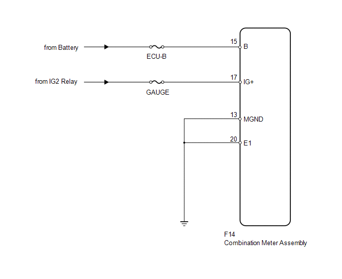
This circuit is the power source circuit for the meter. This circuit provides two types of power sources; one is a constant power source mainly used as a backup power source, and the other is an IG power source mainly used for signal transmission. The constant power source is mainly used as a backup power source for the meter CPU, however, it is also used for CAN communication. If a voltage of 12 V is not applied to terminal IG+ when the ignition switch is turned to ON, the indicators will not operate.
WIRING DIAGRAM
PROCEDURE
|
1. |
CHECK HARNESS AND CONNECTOR |
|
(a) Disconnect the F14 meter connector. |
|
(b) Measure the resistance according to the value(s) in the table below.
Standard Resistance:
|
Tester Connection |
Condition |
Specified Condition |
|---|---|---|
|
F14-20 (E1) - Body ground |
Always |
Below 1 Ω |
|
F14-13 (MGND) - Body ground |
Always |
Below 1 Ω |
(c) Measure the voltage according to the value(s) in the table below.
Standard Voltage:
|
Tester Connection |
Condition |
Specified Condition |
|---|---|---|
|
F14-17 (IG+) - Body ground |
Ignition switch ON |
11 to 14 V |
|
F14-15 (B) - Body ground |
Always |
11 to 14 V |
|
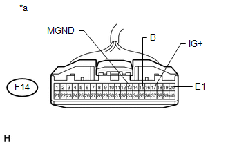
*a |
Front view of wire harness connector (to Combination Meter Assembly) |
| OK | .gif) |
REPLACE COMBINATION METER ASSEMBLY |
| NG | |
REPAIR OR REPLACE HARNESS OR CONNECTOR |
 Lost Communication with ECM / PCM "A" (U0100,U0129,U0131,U0151)
DESCRIPTION
The combination meter assembly communicates with the ECM via the CAN communication
system (CAN No. 1 Bus).
DTC Code.
DTC Detection Condition
Trouble Ar ...
 Speedometer Malfunction
DESCRIPTION
The combination meter receives vehicle speed signals from the skid control ECU
via the CAN communication line. The wheel speed sensors output voltages that vary
according to the vehic ...
Other materials about Toyota 4Runner:
General Maintenance
GENERAL MAINTENANCE
PROCEDURE
1. INSPECT STEERING LINKAGE AND GEAR HOUSING
(a) Check the steering wheel free play.
(b) Check the steering linkage for looseness or damage.
(1) Check that the tie rod ends do not have excessive play.
(2) Check that the dust ...
System Diagram
SYSTEM DIAGRAM
Communication Table
Transmitter
Receiver
Signal
Line
Heater control assembly
Air conditioning amplifier assembly
Defogger switch signal
LIN
...
0.0265