Toyota 4Runner: Front Blower Motor
Components
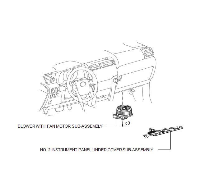
COMPONENTS
ILLUSTRATION
Removal
REMOVAL
PROCEDURE
1. REMOVE NO. 2 INSTRUMENT PANEL UNDER COVER SUB-ASSEMBLY
.gif)
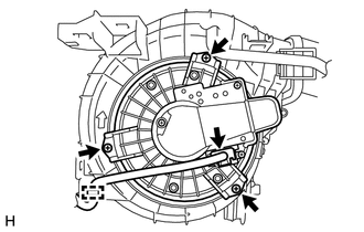
2. REMOVE BLOWER WITH FAN MOTOR SUB-ASSEMBLY
(a) Detach the clamp.
(b) Disconnect the connector.
|
(c) Remove the 3 screws and motor. |
|
Installation
INSTALLATION
PROCEDURE
1. INSTALL BLOWER WITH FAN MOTOR SUB-ASSEMBLY
(a) Install the motor with the 3 screws.
(b) Connect the connector.
(c) Attach the clamp.
2. INSTALL NO. 2 INSTRUMENT PANEL UNDER COVER SUB-ASSEMBLY
.gif)
 Removal
REMOVAL
PROCEDURE
1. DRAIN ENGINE COOLANT
(a) Drain engine coolant (See page ).
2. REMOVE RADIATOR ASSEMBLY
(a) Remove the radiator assembly (See page ).
3. RECOVER REFRIGERANT FROM REFRIGERAT ...

Other materials about Toyota 4Runner:
Removal
REMOVAL
CAUTION / NOTICE / HINT
PROCEDURE
1. REMOVE STEERING WHEEL ASSEMBLY
(a) Remove the steering wheel assembly (See page
).
2. REMOVE LOWER STEERING COLUMN COVER
3. REMOVE UPPER STEERING COLUMN COVER
4. REMOVE SPIRAL CABLE SUB-ASSEMBLY
...
Open or Short in Rear Speed Sensor RH Circuit (C1407,C1408)
DESCRIPTION
Refer to DTCs C1401 and C1402 (See page ).
DTC Code
DTC Detection Condition
Trouble Area
C1407
C1408
Either condition is met:
An open in the speed sensor signal circui ...
0.0127