Toyota 4Runner: Front Passenger Side Door Entry Unlock Function does not Operate
DESCRIPTION
If the front passenger side door entry unlock function does not operate but the entry lock function operates, the communication line between the vehicle and electrical key transmitter is normal. The part at fault may be an unlock sensor circuit (front door outside handle assembly [for front passenger side] → certification ECU).
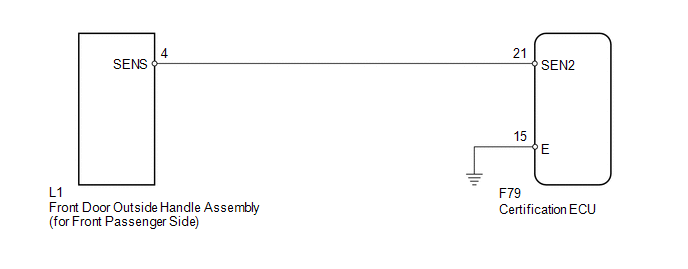
WIRING DIAGRAM
CAUTION / NOTICE / HINT
NOTICE:
- The smart key system (for Entry Function) uses a multiplex communication
system (LIN communication system) and the CAN communication system. Inspect
the communication function by following How to Proceed with Troubleshooting
(See page
.gif) ). Troubleshoot the smart key
). Troubleshoot the smart key
system (for Entry Function) after confirming that the communication systems are functioning properly. - When using the Techstream with the engine switch off to troubleshoot: Connect the Techstream to the DLC3 and turn a courtesy light switch on and off at 1.5-second intervals until communication between the Techstream and vehicle begins.
- Check that there are no electrical key transmitters in the vehicle.
- Before performing the inspection, check that DTC B1242 (wireless door
lock control) is not output (See page ).
- When checking the entry lock operation multiple times, the lock operation may be limited to 2 consecutive operations depending on the settings. In order to perform the entry lock operation 3 or more times, an unlock operation must be performed once (any type of unlock operation is sufficient). However, only consecutive entry lock operations are limited. Using the wireless lock or other types of lock operations, it is possible to perform consecutive lock operations without this limitation.
- Before replacing the certification ECU, refer to the engine immobiliser
system (w/ Smart Key System) (See page
).
PROCEDURE
|
1. |
CHECK POWER DOOR LOCK OPERATION |
(a) When the door control switch on the multiplex network master switch assembly
is operated, check that the doors unlock and lock according to the switch operation
(See page ).
OK:
Door locks operate normally.
| NG | .gif) |
GO TO POWER DOOR LOCK CONTROL SYSTEM |
|
.gif)
|
2. |
READ VALUE USING TECHSTREAM (DOOR LOCK POSITION SWITCH) |
(a) Connect the Techstream to the DLC3.
(b) Turn the engine switch on (IG).
(c) Turn the Techstream on.
(d) Enter the following menus: Body Electrical / Main Body / Data List.
(e) Read the Data List according to the display on the Techstream.
Main Body|
Tester Display |
Measurement Item/Range |
Normal Condition |
Diagnostic Note |
|---|---|---|---|
|
FR Door Lock Pos |
Front RH side door lock position switch signal / UNLOCK or LOCK |
UNLOCK: Front RH side door unlocked LOCK: Front RH side door locked |
- |
OK:
On the Techstream screen, the display changes between LOCK and UNLOCK as shown in the chart above.
| NG | |
GO TO POWER DOOR LOCK CONTROL SYSTEM (Proceed to Only Passenger Door Lock/Unlock Functions do not Operate) |
|
|
3. |
READ VALUE USING TECHSTREAM (UNLOCK SENSOR) |
(a) Using the Techstream, read the Data List (See page
).
Smart Key
|
Tester Display |
Measurement Item/Range |
Normal Condition |
Diagnostic Note |
|---|---|---|---|
|
P-Door Touch Sensor |
Front passenger side door unlock sensor / ON or OFF |
ON: Front passenger side door unlock sensor touched OFF: Front passenger side door unlock sensor not touched |
- |
OK:
"ON" (unlock sensor is touched) and "OFF" (unlock sensor is not touched) appear on the screen.
| OK | |
REPLACE CERTIFICATION ECU |
|
|
4. |
CHECK HARNESS AND CONNECTOR (FRONT DOOR OUTSIDE HANDLE - CERTIFICATION ECU) |
(a) Disconnect the L1 handle connector.
(b) Disconnect the F79 ECU connector.
(c) Measure the resistance according to the value(s) in the table below.
Standard Resistance:
|
Tester Connection |
Condition |
Specified Condition |
|---|---|---|
|
L1-4 (SENS) - F79-21 (SEN2) |
Always |
Below 1 Ω |
|
F79-21 (SEN2) - Body ground |
Always |
10 kΩ or higher |
| NG | |
REPAIR OR REPLACE HARNESS OR CONNECTOR |
|
|
5. |
CHECK FRONT DOOR OUTSIDE HANDLE ASSEMBLY (FOR FRONT PASSENGER SIDE) |
(a) Measure the voltage according to the value(s) in the table below.
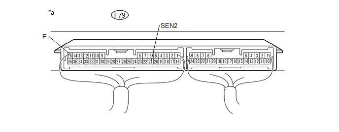 Text in Illustration
|
*a |
Component with harness connected (Certification ECU) |
- |
- |
Standard Voltage:
|
Tester Connection |
Switch Condition |
Specified Condition |
|---|---|---|
|
F79-21 (SEN2) - F79-15 (E) |
Engine switch off, all doors locked, key not sufficiently close to vehicle and unlock sensor (for front passenger side) off → on |
Pulse generation → Below 2 V |
| OK | |
REPLACE CERTIFICATION ECU |
| NG | |
REPLACE FRONT DOOR OUTSIDE HANDLE ASSEMBLY (FOR FRONT PASSENGER SIDE) |
 Driver Side Door Entry Unlock Function does not Operate
DESCRIPTION
If the driver side door entry unlock function does not operate but the entry
lock function operates, the communication line between the vehicle and electrical
key transmitter is norma ...
 Entry Interior Alarm does not Sound
DESCRIPTION
The smart key system uses the combination meter buzzer to perform various vehicle
interior warnings. When the conditions of each warning are met, the certification
ECU sends a buzzer ...
Other materials about Toyota 4Runner:
Lost Communication with Gateway Module (Power Management2) (U1002)
DESCRIPTION
The power management control ECU stores this DTC when no signals can
be received from the ECUs that are memorized as those connected to the power
management bus.
When the power management control ECU receives a response signal f ...
Reassembly
REASSEMBLY
PROCEDURE
1. INSTALL NAVIGATION ANTENNA ASSEMBLY (w/ Navigation System)
2. INSTALL AUTOMATIC LIGHT CONTROL SENSOR
3. INSTALL INSTRUMENT PANEL PASSENGER AIRBAG ASSEMBLY
4. INSTALL NO. 2 INSTRUMENT PANEL WIRE
(a) Attach the 17 clamps to ...
0.0269