Toyota 4Runner: Front Speed Sensor
Components
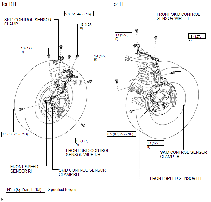
COMPONENTS
ILLUSTRATION
Removal
REMOVAL
CAUTION / NOTICE / HINT
HINT:
- The procedure listed below is for the LH side.
- Other than areas where instructions are provided, use the same procedures for the RH and LH sides.
PROCEDURE
1. REMOVE FRONT WHEEL
2. REMOVE FRONT SKID CONTROL SENSOR WIRE
|
(a) Disconnect the connector from the front speed sensor. |
|
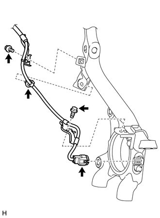
(b) Remove the 2 bolts and 2 harness clamps.
(c) Detach the clip.
|
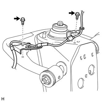
(d) Remove the 2 bolts and 2 harness clamps. |
|
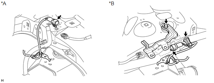
(e) Disconnect the connector as follows.
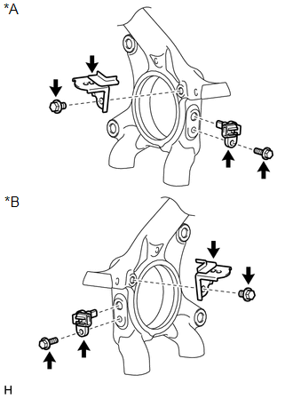
 Text in Illustration
|
*A |
for LH |
*B |
for RH |
(1) for LH:
- Disconnect the connector.
- Detach the connector.
(2) for RH:
- Disconnect the connector.
- Detach the connector from the skid control sensor clamp.
- Detach the clip.
- Remove the bolt and skid control sensor clamp.
3. REMOVE SKID CONTROL SENSOR CLAMP
|
(a) Remove the bolt and skid control sensor clamp from the knuckle. Text in Illustration
|
|
4. REMOVE FRONT SPEED SENSOR
(a) Remove the bolt and speed sensor from the knuckle.
NOTICE:
Pull out the sensor while trying as much as possible not to rotate it.
Inspection
INSPECTION
PROCEDURE
1. CHECK FRONT SPEED SENSOR
(a) Check the sensor.
Under any of the following conditions, replace the sensor with a new one:
- The surface of the sensor is cracked, dented or chipped.
- The connector is scratched, cracked or damaged.
- The sensor has been dropped.
Installation
INSTALLATION
CAUTION / NOTICE / HINT
HINT:
- The procedure listed below is for the LH side.
- Other than areas where instructions are provided, use the same procedures for the RH and LH sides.
PROCEDURE
1. INSTALL FRONT SPEED SENSOR
(a) Install the speed sensor with the bolt.
Torque:
8.5 N·m {87 kgf·cm, 75 in·lbf}
NOTICE:
- Make sure there are no pieces of iron or other foreign matter attached to the sensor tip.
- While inserting the speed sensor into the knuckle hole, do not strike or damage the sensor tip.
- After installing the speed sensor, make sure there is no clearance or foreign matter between the sensor stay part and the knuckle.
- Make sure there is no foreign matter attached to the speed sensor rotor.
2. INSTALL SKID CONTROL SENSOR CLAMP
(a) Install the skid control sensor clamp with the bolt.
Torque:
13 N·m {127 kgf·cm, 9 ft·lbf}
NOTICE:
Install the clamp so that the rotation stopper touches the knuckle.
3. INSTALL FRONT SKID CONTROL SENSOR WIRE
(a) Connect the connector as follows.
(1) for LH:
1. Attach the connector, and then connect the connector.
NOTICE:
Securely connect the connector.
(2) for RH:
1. Install the skid control sensor clamp with the bolt.
Torque:
5.0 N·m {51 kgf·cm, 44 in·lbf}
NOTICE:
Make sure the clamp rotation stopper touches the installation position.
2. Attach the connector, and then connect the connector.
NOTICE:
- Securely connect the connector.
- When connecting the connector, do not twist the wire harness.
3. Attach the clip.
(b) Install the 2 harness clamps with the 2 bolts.
Torque:
13 N·m {127 kgf·cm, 9 ft·lbf}
NOTICE:
- When installing the clamps, do not twist the wire harness.
- Make sure the clamp rotation stopper touches the installation position.
(c) Install the 2 harness clamps with the 2 bolts.
Torque:
13 N·m {127 kgf·cm, 9 ft·lbf}
NOTICE:
- When installing the clamps, do not twist the wire harness.
- Make sure the clamp rotation stopper touches the installation position.
(d) Attach the clip.
(e) Connect the connector.
NOTICE:
Securely connect the connector.
4. INSTALL FRONT WHEEL
.gif)
5. CHECK SPEED SENSOR SIGNAL
(a) Check the speed sensor signal (See page
).
 Downhill Assist Control Switch
Components
COMPONENTS
ILLUSTRATION
Removal
REMOVAL
PROCEDURE
1. REMOVE DRIVE MONITOR SWITCH
2. REMOVE MAP LIGHT ASSEMBLY
3. REMOVE DOWNHILL ASSIST CONTROL SWITCH
(a) Di ...
 Rear Speed Sensor
Components
COMPONENTS
ILLUSTRATION
Removal
REMOVAL
PROCEDURE
1. REMOVE REAR WHEEL
2. REMOVE REAR SPEED SENSOR LH
(a) Disconnect the speed sensor connector.
...
Other materials about Toyota 4Runner:
If the electronic key does not operate properly (vehicles with a smart key
system)
If communication between the electronic key and vehicle is interrupted
or the electronic key cannot be used because the battery is depleted, the smart
key system and wireless remote control cannot be used. In such cases, the doors
can be opened and ...
Disassembly
DISASSEMBLY
PROCEDURE
1. REMOVE BRAKE FLUID INFORMATION LABEL
2. REMOVE BRAKE MASTER CYLINDER RESERVOIR FILLER CAP ASSEMBLY
(a) Remove the brake master cylinder reservoir filler cap assembly from the brake
master cylinder reservoir assembly.
3. REMOVE B ...
0.007