Toyota 4Runner: Downhill Assist Control Switch
Components
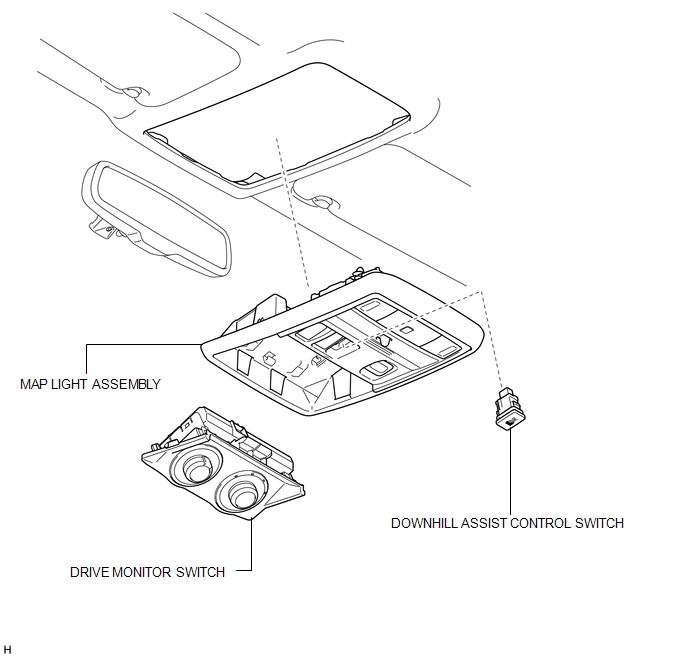
COMPONENTS
ILLUSTRATION
Removal
REMOVAL
PROCEDURE
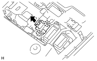
1. REMOVE DRIVE MONITOR SWITCH
.gif)
2. REMOVE MAP LIGHT ASSEMBLY
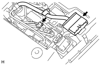
3. REMOVE DOWNHILL ASSIST CONTROL SWITCH
|
(a) Disconnect the 2 connectors. |
|
|
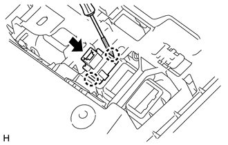
(b) Using a screwdriver, detach the 2 claws and remove the downhill assist control switch from the map light assembly. HINT: Tape the screwdriver tip before use. |
|
Inspection
INSPECTION
PROCEDURE
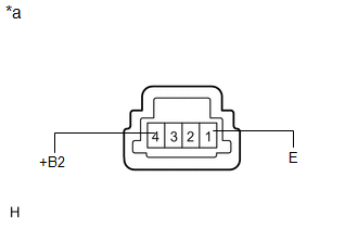
1. CHECK DOWNHILL ASSIST CONTROL SWITCH
|
(a) Measure the resistance according to the value(s) in the table below. Standard Resistance:
If the result is not as specified, replace the downhill assist control switch. |
|
Installation
INSTALLATION
PROCEDURE
1. INSTALL DOWNHILL ASSIST CONTROL SWITCH
|
(a) Attach the 2 claws to install the downhill assist control switch to the map lamp assembly. |
|
(b) Connect the 2 connectors.
2. INSTALL MAP LIGHT ASSEMBLY
.gif)
3. INSTALL DRIVE MONITOR SWITCH
4. PERFORM DOWNHILL ASSIST CONTROL CALIBRATION
(a) Perform downhill assist control switch calibration (See page
).
 Crawl Switch
Components
COMPONENTS
ILLUSTRATION
Removal
REMOVAL
PROCEDURE
1. REMOVE DRIVE MONITOR SWITCH (CRAWL CONTROL SWITCH AND MULTI-TERRAIN SELECT
SWITCH)
(a) Detach the 4 claws and ...
 Front Speed Sensor
Components
COMPONENTS
ILLUSTRATION
Removal
REMOVAL
CAUTION / NOTICE / HINT
HINT:
The procedure listed below is for the LH side.
Other than areas where instructions are provide ...
Other materials about Toyota 4Runner:
Reassembly
REASSEMBLY
CAUTION / NOTICE / HINT
CAUTION:
Wear protective gloves. Sharp areas on the parts may injure your hands.
HINT:
A bolt without a torque specification is shown in the standard bolt chart (See
page ).
PROCEDURE
1. INSTALL REAR SEAT TRACK ADJU ...
Installation
INSTALLATION
PROCEDURE
1. INSTALL PROPELLER SHAFT ASSEMBLY
(a) Align the matchmarks on the propeller shaft flange and differential flange.
(b) Install the propeller shaft assembly with the 4 washers, 4 bolts and 4 nuts.
Torque:
88 N·m {899 kgf·cm, 65 ...
0.0078