Toyota 4Runner: Generator Signal Circuit
DESCRIPTION
When the engine is started, the generator assembly turns on and a voltage pulse signal is generated.
This signal is used by the air conditioning amplifier assembly.
The signal expressing the amount of output from the generator assembly is one element of PTC heater control.
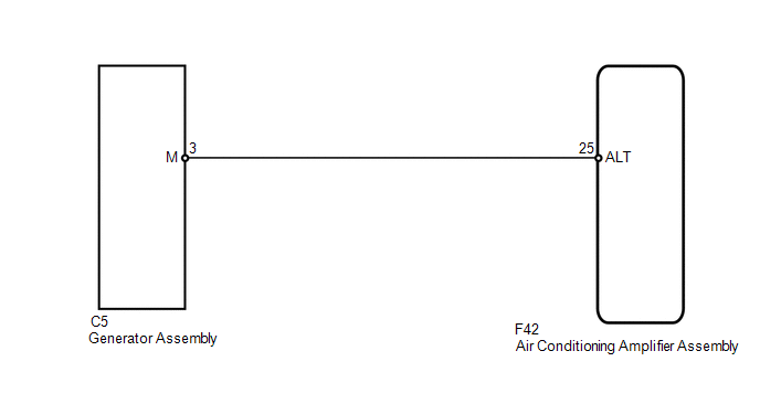
WIRING DIAGRAM
PROCEDURE
|
1. |
CHECK HARNESS AND CONNECTOR (AIR CONDITIONING AMPLIFIER - GENERATOR) |
(a) Disconnect the F42 amplifier connector.
(b) Disconnect the C5 generator connector.
(c) Measure the resistance according to the value(s) in the table below.
Standard Resistance:
|
Tester Connection |
Condition |
Specified Condition |
|---|---|---|
|
F42-25 (ALT) - C5-3 (M) |
Always |
Below 1 Ω |
|
F42-25 (ALT) - Body ground |
Always |
10 kΩ or higher |
| OK | .gif) |
PROCEED TO NEXT SUSPECTED AREA SHOWN IN PROBLEM SYMPTOMS TABLE |
| NG | |
REPAIR OR REPLACE HARNESS OR CONNECTOR |
 Air Conditioning Compressor Magnetic Clutch Circuit
DESCRIPTION
When the air conditioning amplifier assembly is turned on, a magnet clutch assembly
signal is sent from the MGC terminal of the air conditioning amplifier assembly.
Then, the A/C COMP ...
 PTC Heater Circuit
DESCRIPTION
PTC heater relays are closed in accordance with signals from the air conditioning
amplifier assembly and power is supplied to the quick heater assembly installed
on the radiator heate ...
Other materials about Toyota 4Runner:
Problem Symptoms Table
PROBLEM SYMPTOMS TABLE
HINT:
Use the table below to help determine the cause of problem symptoms. If multiple
suspected areas are listed, the potential causes of the symptoms are listed in order
of probability in the "Suspected Area" column of ...
How To Proceed With Troubleshooting
CAUTION / NOTICE / HINT
HINT:
Use the following procedures to troubleshoot the key reminder warning
system.
*: Use the Techstream.
PROCEDURE
1.
VEHICLE BROUGHT TO WORKSHOP
NEXT
...
0.0277