Toyota 4Runner: ID Code Box Power Source Circuit
DESCRIPTION
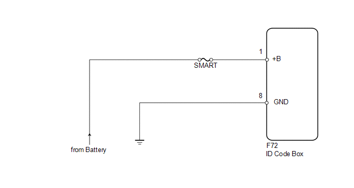
This circuit provides power to operate the ID code box.
WIRING DIAGRAM
CAUTION / NOTICE / HINT
NOTICE:
Inspect the fuses for circuits related to this system before performing the following inspection procedure.
PROCEDURE
|
1. |
CHECK HARNESS AND CONNECTOR (ID CODE BOX - BATTERY AND BODY GROUND) |
|
(a) Disconnect the F72 box connector. |
|
.png)
(b) Measure the voltage according to the value(s) in the table below.
Standard Voltage:
|
Tester Connection |
Condition |
Specified Condition |
|---|---|---|
|
F72-1 (+B) - Body ground |
Always |
11 to 14 V |
(c) Measure the resistance according to the value(s) in the table below.
Standard Resistance:
|
Tester Connection |
Condition |
Specified Condition |
|---|---|---|
|
F72-8 (GND) - Body ground |
Always |
Below 1 Ω |
|
*a |
Front view of wire harness connector (to ID Code Box) |
| OK | .gif) |
PROCEED TO NEXT SUSPECTED AREA SHOWN IN PROBLEM SYMPTOMS TABLE |
| NG | |
REPAIR OR REPLACE HARNESS OR CONNECTOR |
 Certification ECU Power Source Circuit
DESCRIPTION
This circuit provides power to the certification ECU.
WIRING DIAGRAM
CAUTION / NOTICE / HINT
NOTICE:
Inspect the fuses for circuits related to this system before performing the foll ...
 Security Indicator Light Circuit
DESCRIPTION
When the engine immobiliser system is set, the security indicator flashes
continuously, but does not illuminate if the engine immobiliser system is
not set.
WIRING D ...
Other materials about Toyota 4Runner:
XM® Satellite Radio (if equipped)
Receiving XM® Satellite Radio
Press
or
.
The display changes as follows each time
or
is pressed.
Type A: AM → SAT1 → SAT2 → SAT3 Type B and C: AM → FM → SAT
Turn
or
to select the desired channel in all
the categories or press “� ...
Cleaning and protecting the vehicle exterior
Perform the following to protect the vehicle and maintain it in prime
condition:
• Working from top to bottom, liberally apply water to the vehicle body,
wheel wells and underside of the vehicle to remove any dirt and dust.
• Wash the vehicle body u ...
0.0087