Toyota 4Runner: Certification ECU Power Source Circuit
DESCRIPTION
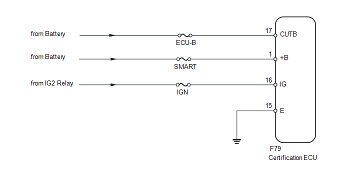
This circuit provides power to the certification ECU.
WIRING DIAGRAM
CAUTION / NOTICE / HINT
NOTICE:
Inspect the fuses for circuits related to this system before performing the following inspection procedure.
PROCEDURE
|
1. |
CHECK HARNESS AND CONNECTOR (CERTIFICATION ECU - BATTERY AND BODY GROUND) |
|
(a) Disconnect the F79 ECU connector. |
|
(b) Measure the voltage according to the value(s) in the table below.
Standard Voltage:
|
Tester Connection |
Switch Condition |
Specified Condition |
|---|---|---|
|
F79-1 (+B) - Body ground |
Always |
11 to 14 V |
|
F79-16 (IG) - Body ground |
Engine switch off |
Below 1 V |
|
F79-16 (IG) - Body ground |
Engine switch on (IG) |
11 to 14 V |
|
F79-17 (CUTB) - Body ground |
Always |
11 to 14 V |
(c) Measure the resistance according to the value(s) in the table below.
Standard Resistance:
|
Tester Connection |
Condition |
Specified Condition |
|---|---|---|
|
F79-15 (E) - Body ground |
Always |
Below 1 Ω |
|
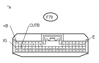
*a |
Front view of wire harness connector (to Certification ECU) |
| OK | .gif) |
PROCEED TO NEXT SUSPECTED AREA SHOWN IN PROBLEM SYMPTOMS TABLE |
| NG | |
REPAIR OR REPLACE HARNESS OR CONNECTOR |
 Engine Immobiliser System Malfunction (B2799)
DESCRIPTION
This DTC is stored when one of the following occurs: 1) the ECM detects errors
in its own communications with the ID code box; 2) the ECM detects errors in the
communication lines; or ...
 ID Code Box Power Source Circuit
DESCRIPTION
This circuit provides power to operate the ID code box.
WIRING DIAGRAM
CAUTION / NOTICE / HINT
NOTICE:
Inspect the fuses for circuits related to this system before performing the fo ...
Other materials about Toyota 4Runner:
Removal
REMOVAL
PROCEDURE
1. DRAIN AUTOMATIC TRANSMISSION FLUID
2. REMOVE AUTOMATIC TRANSMISSION OIL PAN SUB-ASSEMBLY
3. REMOVE VALVE BODY OIL STRAINER ASSEMBLY
4. DISCONNECT TRANSMISSION WIRE
5. REMOVE TRANSMISSION VALVE BODY ASSEMBLY
(a) Remove th ...
Reassembly
REASSEMBLY
CAUTION / NOTICE / HINT
HINT:
Use the same procedure for the RH and LH sides.
The procedure listed below is for the LH side.
PROCEDURE
1. TEMPORARILY INSTALL FRONT DISC BRAKE BLEEDER PLUG
(a) Temporarily install the front dis ...
0.0065