Toyota 4Runner: Ignition Hold Monitor Malfunction (B2271)
DESCRIPTION
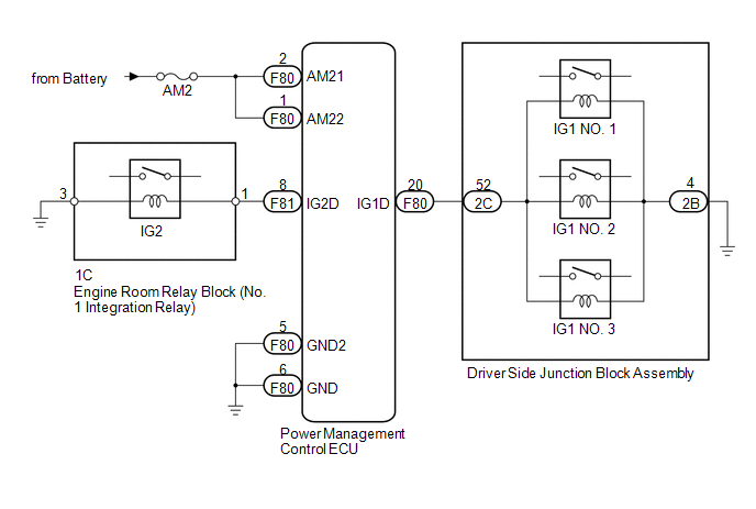
This DTC is stored when a problem, such as an open in the AM2 fuse, an open or short in the wire harness between the fuse and power management control ECU, a short in the IG output circuit inside the power management control ECU, a short between the power management control ECU and relay, or a short in the relay, is detected.
HINT:
When the power management control ECU is replaced with a new one and the cable is connected to the negative (-) battery terminal, the power source mode is reset to on (IG). When the battery is removed and reinstalled, the power source mode that was selected when the battery was removed is restored.
|
DTC Code |
DTC Detection Condition |
Trouble Area |
|---|---|---|
|
B2271 |
The hold circuit, IG1 relay actuation circuit or IG2 relay actuation circuit inside the power management control ECU is open or shorted. |
|
WIRING DIAGRAM
CAUTION / NOTICE / HINT
NOTICE:
- When using the Techstream with the engine switch off to troubleshoot: Connect the Techstream to the vehicle and turn a courtesy light switch on and off at 1.5 second intervals until communication between the Techstream and vehicle begins.
- Before performing the inspection, check that there are no problems related to the CAN communication system and LIN communication system.
- Inspect the fuses for circuits related to this system before performing the following inspection procedure.
PROCEDURE
|
1. |
CHECK HARNESS AND CONNECTOR (BATTERY - POWER MANAGEMENT CONTROL ECU) |
|
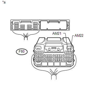
(a) Disconnect the F80 power management control ECU connector. |
|
(b) Measure the voltage according to the value(s) in the table below.
Standard Voltage:
|
Tester Connection |
Condition |
Specified Condition |
|---|---|---|
|
F80-2 (AM21) - Body ground |
Always |
9.5 to 14 V |
|
F80-1 (AM22) - Body ground |
|
*a |
Rear view of wire harness connector (to Power Management Control ECU) |
| NG | .gif) |
REPAIR OR REPLACE HARNESS OR CONNECTOR |
|
.gif)
|
2. |
CHECK HARNESS AND CONNECTOR (POWER MANAGEMENT CONTROL ECU - BODY GROUND) |
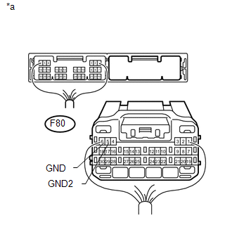
(a) Disconnect the F80 power management control ECU connector.
|
(b) Measure the resistance according to the value(s) in the table below. Standard Resistance:
|
|
| NG | |
REPAIR OR REPLACE HARNESS OR CONNECTOR |
|
|
3. |
INSPECT NO. 1 INTEGRATION RELAY (IG2 RELAY) |
|
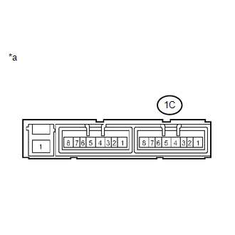
(a) Remove the No. 1 integration relay. |
|
(b) Measure the resistance according to the value(s) in the table below.
Standard Resistance:
|
Tester Connection |
Condition |
Specified Condition |
|---|---|---|
|
1C-1 - 1C-3 |
20°C (68°F) |
255 to 387 Ω |
|
*a |
Component without harness connected (No. 1 Integration Relay) |
| NG | |
REPLACE NO. 1 INTEGRATION RELAY |
|
|
4. |
INSPECT DRIVER SIDE JUNCTION BLOCK ASSEMBLY (IG1 NO. 1, IG1 NO. 2 AND IG1 NO. 3 RELAYS) |
|
(a) Remove the driver side junction block assembly. |
|
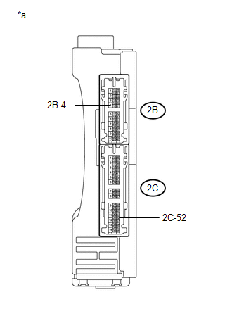
(b) Measure the resistance according to the value(s) in the table below.
Standard Resistance:
|
Tester Connection |
Condition |
Specified Condition |
|---|---|---|
|
2C-52 - 2B-4 |
20°C (68°F) |
101.25 to 123.75 Ω |
|
*a |
Component without harness connected (Driver Side Junction Block Assembly) |
| NG | |
REPLACE MAIN BODY ECU (DRIVER SIDE JUNCTION BLOCK ASSEMBLY) |
|
|
5. |
CHECK HARNESS AND CONNECTOR (POWER MANAGEMENT CONTROL ECU - DRIVER SIDE JUNCTION BLOCK ASSEMBLY) |
(a) Disconnect the F80 power management control ECU connector.
(b) Disconnect the 2C driver side junction block assembly connector.
(c) Measure the resistance according to the value(s) in the table below.
Standard Resistance:
|
Tester Connection |
Condition |
Specified Condition |
|---|---|---|
|
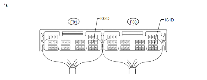
F80-20 (IG1D) - 2C-52 |
Always |
Below 1 Ω |
|
F80-20 (IG1D) - Body ground |
Always |
10 kΩ or higher |
| NG | |
REPAIR OR REPLACE HARNESS OR CONNECTOR |
|
|
6. |
CHECK HARNESS AND CONNECTOR (DRIVER SIDE JUNCTION BLOCK ASSEMBLY - BODY GROUND) |
(a) Disconnect the 2B driver side junction block assembly connector.
(b) Measure the resistance according to the value(s) in the table below.
Standard Resistance:
|
Tester Connection |
Condition |
Specified Condition |
|---|---|---|
|
2B-4 - Body ground |
Always |
Below 1 Ω |
| NG | |
REPAIR OR REPLACE HARNESS OR CONNECTOR |
|
|
7. |
CHECK HARNESS AND CONNECTOR (POWER MANAGEMENT CONTROL ECU - NO. 1 INTEGRATION RELAY) |
(a) Disconnect the F81 power management control ECU connector.
(b) Disconnect the 1C No. 1 integration relay connector.
(c) Measure the resistance according to the value(s) in the table below.
Standard Resistance:
|
Tester Connection |
Condition |
Specified Condition |
|---|---|---|
|
F81-8 (IG2D) - 1C-1 |
Always |
Below 1 Ω |
|
F81-8 (IG2D) - Body ground |
Always |
10 kΩ or higher |
| NG | |
REPAIR OR REPLACE HARNESS OR CONNECTOR |
|
|
8. |
CHECK HARNESS AND CONNECTOR (NO. 1 INTEGRATION RELAY - BODY GROUND) |
(a) Disconnect the 1C No. 1 integration relay connector.
(b) Measure the resistance according to the value(s) in the table below.
Standard Resistance:
|
Tester Connection |
Condition |
Specified Condition |
|---|---|---|
|
1C-3 - Body ground |
Always |
Below 1 Ω |
| NG | |
REPAIR OR REPLACE HARNESS OR CONNECTOR |
|
|
9. |
CHECK POWER MANAGEMENT CONTROL ECU |
(a) Install the No. 1 integration relay.
(b) Install the driver side junction block assembly.
(c) Connect the power management control ECU connectors.
 Text in Illustration
|
*a |
Component with harness connected (Power Management Control ECU) |
- |
- |
(d) Measure the voltage according to the value(s) in the table below.
Standard Voltage:
|
Tester Connection |
Switch Condition |
Specified Condition |
|---|---|---|
|
F81-8 (IG2D) - Body ground |
Engine switch off |
Below 1 V |
|
Engine switch on (IG) |
((Voltage at terminal AM21 or AM22) minus 2.0 V) or higher |
|
|
F80-20 (IG1D) - Body ground |
Engine switch off |
Below 1 V |
|
Engine switch on (IG) |
((Voltage at terminal AM21 or AM22) minus 2.0 V) or higher |
| OK | |
USE SIMULATION METHOD TO CHECK |
| NG | |
REPLACE POWER MANAGEMENT CONTROL ECU |
 Lost Communication with ECM / PCM (U0100,U0129,U0142,U0155)
DESCRIPTION
The power management control ECU receives information from 2 sources. It receives
information via a direct line and via the CAN communication line. If the information
from these 2 sou ...
 Brake Signal Malfunction (B2284)
DESCRIPTION
This DTC is stored when the brake signal information from the cable and the brake
signal information from the CAN communication line are inconsistent
HINT:
When the power management c ...
Other materials about Toyota 4Runner:
Trip information
Items displayed can be switched by pressing the “MODE/
” button.
Driving range
Displays the estimated maximum distance that can be driven with the quantity
of fuel remaining
• This distance is computed based on your average fuel consumption. As a ...
Inverter Main Switch
Components
COMPONENTS
ILLUSTRATION
Installation
INSTALLATION
PROCEDURE
1. INSTALL MAIN SWITCH ASSEMBLY
(a) Attach the 2 claws to install the main switch.
2. INSTALL LOWER INSTRUMENT PANEL FINISH PANEL SUB-ASSEMBLY
3. INSTALL COWL SIDE TRIM BO ...
0.027