Toyota 4Runner: Inspection
INSPECTION
PROCEDURE
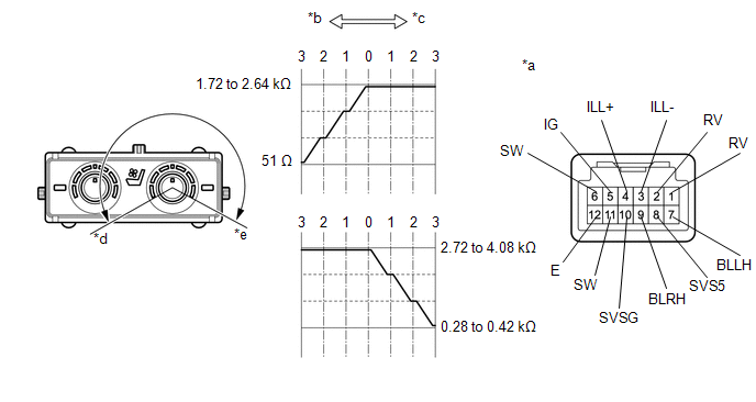
1. INSPECT REFRESHING SEAT SWITCH
 Text in Illustration
|
*a |
Component without harness connected (Refreshing Seat Switch) |
*b |
Blower |
|
*c |
Heater |
*d |
Blower Max. |
|
*e |
Heater Max. |
- |
- |
(a) Measure the resistance according to the value(s) in the table below.
Standard Resistance:
for LH Side
|
Tester Connection |
Switch Condition |
Specified Condition |
|---|---|---|
|
7 (BLLH) - 10 (SVSG) |
Switch off |
1.72 to 2.64 kΩ |
|
Switch on (Blower Min.) |
||
|
Switch on (Blower Max.) |
Below 510 Ω |
|
|
6 (SW) - 1 (RV) |
Switch off |
2.72 to 4.08 kΩ |
|
Switch on (Heater Min.) |
||
|
Switch on (Heater Max.) |
0.28 to 0.42 kΩ |
Standard Resistance:
for RH Side
|
Tester Connection |
Switch Condition |
Specified Condition |
|---|---|---|
|
9 (BLRH) - 10 (SVSG) |
Switch off |
1.72 to 2.64 kΩ |
|
Switch on (Blower Min.) |
||
|
Switch on (Blower Max.) |
Below 51 Ω |
|
|
11 (SW) - 2 (RV) |
Switch off |
2.72 to 4.08 kΩ |
|
Switch on (Heater Min.) |
||
|
Switch on (Heater Max.) |
0.28 to 0.42 kΩ |
HINT:
As the dial is being turned, the resistance changes gradually.
If the result is not as specified, replace the refreshing seat switch.
(b) Apply battery voltage to the switch connector and check that the refreshing seat switch illuminates.
OK:
|
Measurement Condition |
Specified Condition |
|---|---|
|
Battery positive (+) → 4 (ILL+) Battery negative (-) → 3 (ILL-) |
Illuminates |
If the result is not as specified, replace the refreshing seat switch.
(c) Apply battery voltage to the switch connector and check that the refreshing seat switch indicator illuminates.
OK:
|
Measurement Condition |
Switch Condition |
Specified Condition |
|---|---|---|
|
Battery positive (+) → 5 (IG) Battery negative (-) → 12 (E) |
Switch on |
Indicator illuminates |
If the result is not as specified, replace the refreshing seat switch.
 Removal
REMOVAL
PROCEDURE
1. DISCONNECT CABLE FROM NEGATIVE BATTERY TERMINAL
CAUTION:
Wait at least 90 seconds after disconnecting the cable from the negative (-)
battery terminal to disable the SRS sys ...
 Installation
INSTALLATION
PROCEDURE
1. INSTALL REFRESHING SEAT SWITCH
(a) Attach the 4 claws to install the refreshing seat switch.
2. INSTALL LOWER CENTER INSTRUMENT CLUSTER FINISH PANEL SUB-ASSEMBLY
3. I ...
Other materials about Toyota 4Runner:
Ultrasonic Sensor(for Front)
Components
COMPONENTS
ILLUSTRATION
ILLUSTRATION
Removal
REMOVAL
PROCEDURE
1. REMOVE UPPER RADIATOR SUPPORT SEAL
2. REMOVE FRONT BUMPER COVER
3. REMOVE NO. 2 ENGINE ROOM WIRE
4. REMOVE NO. 1 ULTRASONIC SENSOR
(a) Detach th ...
Installation
INSTALLATION
PROCEDURE
1. INSTALL NO. 1 ULTRASONIC SENSOR RETAINER
(a) Align the keyhole and protrusion as shown in the illustration.
Text in Illustration
*1
Keyhole
...
0.0267