Toyota 4Runner: Installation
INSTALLATION
PROCEDURE
1. INSTALL RACK AND PINION POWER STEERING GEAR ASSEMBLY
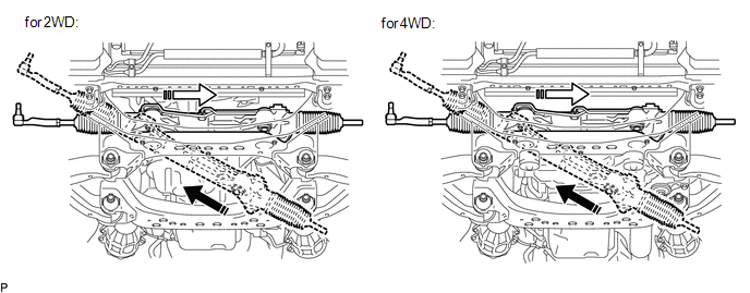
(a) Insert the power steering gear assembly into the vehicle in the order shown in the illustration.
.png) |
Install in this Direction (1) |
.png) |
Install in this Direction (2) |
|
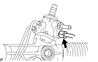
(b) Temporarily connect the pressure feed tube to the power steering gear. |
|
|
(c) Install the pressure feed tube clamp with the 2 bolts. Torque: 28 N·m {286 kgf·cm, 21 ft·lbf} |
|
.png)
|
(d) Using a union nut wrench, tighten the pressure feed tube (pressure feed tube side). Torque: 25 N·m {255 kgf·cm, 18 ft·lbf} NOTICE:
|
|
|
(e) Connect the pressure feed tube (return tube side) to the steering gear with the clamp. NOTICE: Do not damage the pressure feed tube. |
|
.png)
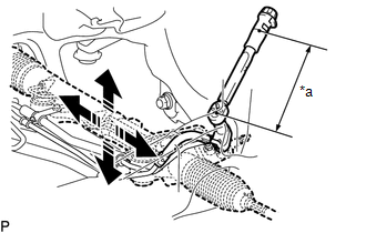
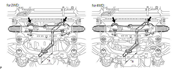
(f) Install the power steering gear with the 2 bolts and 2 nuts.
SST: 09961-01270
Torque:
Specified tightening torque :
120 N·m {1224 kgf·cm, 89 ft·lbf}
HINT:
- Calculate the torque wrench reading when changing the fulcrum length of the torque wrench.
- When using SST (fulcrum length of 200 mm (7.874 in.)) + torque wrench (fulcrum length of 380 mm (14.961 in.)): 78.6 N*m (801 kgf*cm, 58 ft.*lbf)
- Hold the nuts and tighten the bolts to install the power steering link.
|
*a |
Torque Wrench Fulcrum Length |
- |
- |
2. INSTALL COOLER COMPRESSOR ASSEMBLY
|
(a) Temporary install the 3 bolts and nut. |
|
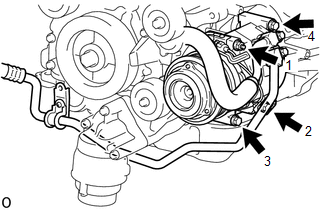
(b) Tighten the 3 bolts and nut in the order shown in the illustration.
Torque:
25 N·m {255 kgf·cm, 18 ft·lbf}
|
(c) Install the suction hose sub-assembly with the bolt. Torque: 7.8 N·m {80 kgf·cm, 69 in·lbf} |
|
.png)
(d) Install the fan and generator V belt.
Click here .gif)
3. INSTALL FRONT DIFFERENTIAL CARRIER ASSEMBLY (for 4WD)
Click here
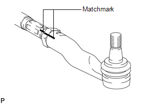
4. INSTALL TIE ROD END SUB-ASSEMBLY LH
(a) Align the matchmarks of the tie rod and rack end and temporarily install the tie rod with the lock nut.
|
(b) After adjusting toe-in, torque the nut. Torque: 82 N·m {836 kgf·cm, 60 ft·lbf} |
|
5. CONNECT TIE ROD END SUB-ASSEMBLY LH
(a) Connect the tie rod end to the steering knuckle with the nut.
Torque:
91 N·m {928 kgf·cm, 67 ft·lbf}
NOTICE:
Tighten the nut up to an additional 60° if the holes for the cotter pin are not aligned.
(b) Install a new cotter pin.
6. CONNECT TIE ROD END SUB-ASSEMBLY RH
HINT:
Use the same procedures described for the LH side.
7. CONNECT NO. 2 STEERING INTERMEDIATE SHAFT
(a) Connect the No. 2 steering intermediate shaft (See page
).
8. INSTALL REAR ENGINE UNDER COVER ASSEMBLY
Click here
9. INSTALL NO. 1 ENGINE UNDER COVER
Click here
10. ADD POWER STEERING FLUID
11. BLEED AIR FROM POWER STEERING FLUID
(a) Bleed air from the power steering fluid (See page
).
12. CHECK FOR POWER STEERING FLUID LEAK
13. INSTALL FRONT WHEELS
Torque:
for aluminum wheel :
103 N·m {1050 kgf·cm, 76 ft·lbf}
for steel wheel :
112 N·m {1142 kgf·cm, 83 ft·lbf}
14. PLACE FRONT WHEELS FACING STRAIGHT AHEAD
15. ADJUST FRONT WHEEL ALIGNMENT
(a) Adjust the front wheel alignment (See page
).
 Reassembly
REASSEMBLY
PROCEDURE
1. INSTALL STEERING RACK END SUB-ASSEMBLY
(a) Temporarily install the 2 steering rack ends to the steering rack.
(b) Fill up the ball joints of the steering rack ends with MP ...

Other materials about Toyota 4Runner:
Removal
REMOVAL
CAUTION / NOTICE / HINT
HINT:
Use the same procedure for the RH and LH sides.
The procedure listed below is for the LH side.
PROCEDURE
1. REMOVE FRONT WHEEL
2. REMOVE SKID CONTROL SENSOR WIRE
3. REMOVE FRONT SUSPENSION UPPER ...
Reassembly
REASSEMBLY
PROCEDURE
1. INSTALL STEERING RACK END SUB-ASSEMBLY
(a) Temporarily install the 2 steering rack ends to the steering rack.
(b) Fill up the ball joints of the steering rack ends with MP grease.
(c) Using SST, install the steering rack ...
0.0272