Toyota 4Runner: Installation
INSTALLATION
PROCEDURE
1. INSTALL BRAKE PEDAL SUPPORT ASSEMBLY
(a) Temporarily install the set bolt.
(b) Install the hydraulic brake booster (See page
.gif) ).
).
(c) tighten the brake pedal support sub-assembly with the 4 nuts.
Torque:
14 N·m {145 kgf·cm, 10 ft·lbf}
(d) Tighten the brake pedal support reinforcement set bolt.
Torque:
20 N·m {204 kgf·cm, 15 ft·lbf}
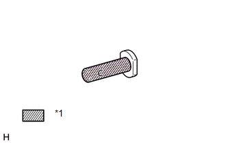
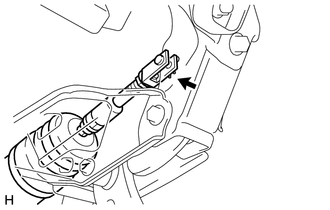
2. INSTALL PUSH ROD PIN
|
(a) Apply a light coat of lithium soap base glycol grease to the inner surface of the hole in the brake pedal lever. Text in Illustration
|
|
|
(b) Set the master cylinder push rod clevis in place, insert the push rod pin from the left side of the vehicle, and then install a new clip. |
|
3. INSTALL BRAKE PEDAL RETURN SPRING
(a) Apply a light coat of lithium soap base glycol grease to inner surface of the hole in the brake pedal support sub-assembly.
(b) Install the brake pedal return spring to the brake pedal support sub-assembly.
4. INSTALL STOP LIGHT SWITCH ASSEMBLY
(a) Install the stop light switch (See page
).
(b) Connect the stop light switch connector.
5. INSTALL LOWER NO. 1 INSTRUMENT PANEL AIRBAG ASSEMBLY
(a) Install the lower No. 1 instrument panel airbag assembly (See page
).
6. CONNECT CABLE FROM NEGATIVE BATTERY TERMINAL
NOTICE:
When disconnecting the cable, some systems need to be initialized after the cable
is reconnected (See page ).
7. BLEED BRAKE SYSTEM
8. CHECK AND ADJUST BRAKE PEDAL
(a) Check and adjust brake pedal (See page ).
 Reassembly
REASSEMBLY
PROCEDURE
1. INSTALL STOP LIGHT SWITCH MOUNTING ADJUSTER
(a) Install a new stop light switch mounting adjuster to the brake pedal support.
2. INSTALL BRAKE PEDAL PAD
(a) Install the br ...

Other materials about Toyota 4Runner:
Relay(for Windshield Deicer)
On-vehicle Inspection
ON-VEHICLE INSPECTION
PROCEDURE
1. REMOVE DEICER RELAY (DEICER)
(a) Remove the deicer relay from the engine room relay block.
Text in Illustration
*1
Deicer Relay
...
Front Blower Motor
Components
COMPONENTS
ILLUSTRATION
Removal
REMOVAL
PROCEDURE
1. REMOVE NO. 2 INSTRUMENT PANEL UNDER COVER SUB-ASSEMBLY
2. REMOVE BLOWER WITH FAN MOTOR SUB-ASSEMBLY
(a) Detach the clamp.
(b) Disconnect the connector.
(c) Remove the ...
0.0269