Toyota 4Runner: Installation
INSTALLATION
PROCEDURE
1. INSTALL BRAKE BOOSTER GASKET
(a) Install a new brake booster gasket to the hydraulic brake booster.
2. INSTALL HYDRAULIC BRAKE BOOSTER ASSEMBLY
(a) Install the hydraulic brake booster assembly with the 4 nuts.
Torque:
14 N·m {145 kgf·cm, 10 ft·lbf}
|
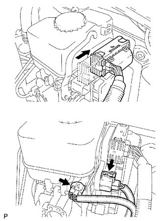
(b) Connect the 4 brake lines to the correct positions of the hydraulic brake booster assembly as shown in the illustration. HINT:
|
|
.png)
(c) Using a union nut wrench, connect the 4 brake lines to the hydraulic brake booster assembly.
Torque:
15 N·m {155 kgf·cm, 11 ft·lbf}
NOTICE:
Use the formula to calculate special torque values for situations where a union
nut wrench is combined with a torque wrench (See page
.gif) ).
).
|
(d) Connect the 3 connectors to the hydraulic brake booster assembly. |
|
3. INSTALL PUSH ROD PIN
4. INSTALL LOWER NO. 1 INSTRUMENT PANEL AIRBAG ASSEMBLY
(a) Install the lower No. 1 instrument panel airbag assembly (See page
).
5. CONNECT CABLE TO NEGATIVE BATTERY TERMINAL
NOTICE:
When disconnecting the cable, some systems need to be initialized after the cable
is reconnected (See page ).
6. BLEED BRAKE SYSTEM
7. CHECK AND ADJUST BRAKE PEDAL
(a) Check and adjust brake pedal (See page ).
8. INSPECT BRAKE MASTER CYLINDER OPERATION
(a) Inspect the brake master cylinder operation (See page
).
9. PERFORM YAW RATE AND ACCELERATION SENSOR ZERO POINT CALIBRATION
(a) Perform the yaw rate and acceleration sensor zero point calibration (See
page ).
 Reassembly
REASSEMBLY
PROCEDURE
1. INSTALL BRAKE BOOSTER PISTON SIB-ASSEMBLY
(a) Apply a light coat of lithium soap base glycol grease to a new piston.
(b ...
 Disposal
DISPOSAL
PROCEDURE
1. DISPOSE OF BRAKE BOOSTER ACCUMULATOR ASSEMBLY
(a) Place the brake booster accumulator assembly in a vise and cover
it with cloth.
...
Other materials about Toyota 4Runner:
How To Proceed With Troubleshooting
CAUTION / NOTICE / HINT
HINT:
Use these procedures to troubleshoot the power door lock control system.
*: Use the Techstream.
PROCEDURE
1.
VEHICLE BROUGHT TO WORKSHOP
NEXT
...
LIN Communication Bus Malfunction (B2325)
DESCRIPTION
The main body ECU (multiplex network body ECU) intermittently monitors the LIN
communication bus between the components related to the doors and sliding roof ECU
(sliding roof drive gear sub-assembly)*. DTC B2325 is stored when a malfunction
...
0.026