Toyota 4Runner: Installation
INSTALLATION
PROCEDURE
1. INSTALL TORQUE CONVERTER CLUTCH ASSEMBLY
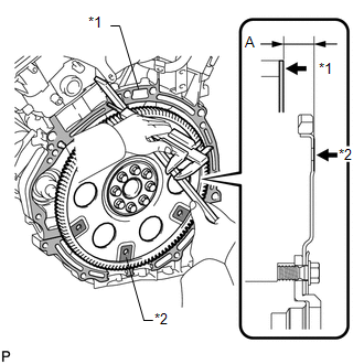
(a) Using a vernier caliper and straightedge, measure dimension "A" between the transmission fitting surface of the engine*1 and the torque converter clutch fitting surface of the drive plate*2 (step 1).
|
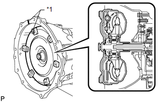
(b) Align the matchmarks on the transmission case and torque converter clutch, and then mesh the splines of the input shaft and turbine runner. Text in Illustration
|
|
|
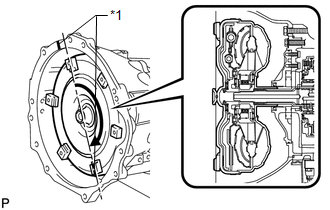
(c) Mesh the splines of the stator shaft and stator while turning the torque converter clutch. Text in Illustration
HINT: Turn the torque converter clutch approximately 180°. |
|
|
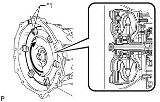
(d) Turn the torque converter clutch and align the matchmarks on the torque converter clutch and transmission case to fit the key of the oil pump drive gear into the slot on the torque converter clutch. Text in Illustration
NOTICE: Do not push on the torque converter clutch when aligning the matchmarks. |
|
|
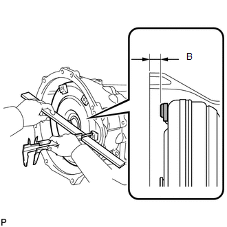
(e) Using a vernier caliper and straightedge, measure dimension B shown in the illustration and check that B is more than A (measured in step 1). Standard distance: A + 1 mm (0.0394 in.) or more |
|
2. INSTALL NO. 1 TRANSMISSION CONTROL CABLE BRACKET
(a) Install the No. 1 transmission control cable bracket with the 2 bolts.
Torque:
14 N·m {143 kgf·cm, 10 ft·lbf}
3. INSTALL WIRE HARNESS CLAMP BRACKET
(a) Install the 4 brackets with the 4 bolts.
Torque:
8.0 N·m {82 kgf·cm, 71 in·lbf}
4. INSTALL AUTOMATIC TRANSMISSION ASSEMBLY
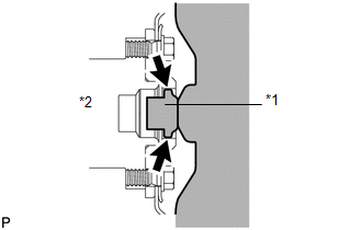
(a) Apply clutch spline grease to the surface of the crankshaft that contacts the torque converter clutch centerpiece.
Clutch spline grease:
Toyota Genuine Clutch Spline Grease or equivalent
Maximum grease amount
Approximately 1 g (0.0353 oz.)
Text in Illustration|
*1 |
Torque Converter Clutch Centerpiece |
|
*2 |
Crankshaft |
|
(b) Confirm that the 2 knock pins are on the transmission contact surface of the engine block before transmission installation. |
|
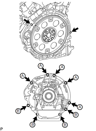
(c) Install the automatic transmission with the 9 bolts.
Torque:
for 17 mm head bolt A :
71 N·m {724 kgf·cm, 52 ft·lbf}
for 14 mm head bolt B :
37 N·m {377 kgf·cm, 27 ft·lbf}
5. CONNECT BREATHER PLUG HOSE
(a) Connect the breather plug hose to the engine.
6. CONNECT WIRE HARNESS AND CONNECTOR
(a) Connect the park/neutral start switch connector, transmission wire connector and 2 speed sensor connectors.
HINT:
Push up the lever until the claw of the transmission wire connector makes a connection sound.
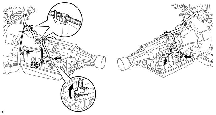
(b) Connect the 2 connector clamps and 4 harness clamps.
(c) Tilt up the automatic transmission.
7. INSTALL REAR NO. 1 ENGINE MOUNTING INSULATOR
(a) Install the rear No. 1 engine mounting insulator to the transmission with the 4 bolts.
Torque:
72.5 N·m {739 kgf·cm, 53 ft·lbf}
(b) Install the rear engine mounting heat insulator to the engine mounting insulator.
Torque:
12 N·m {122 kgf·cm, 9 ft·lbf}
8. INSTALL NO. 3 FRAME CROSSMEMBER SUB-ASSEMBLY
(a) Install the No. 3 frame crossmember sub-assembly to the rear engine mounting insulator with the 4 bolts.
Torque:
30 N·m {306 kgf·cm, 22 ft·lbf}
(b) Install the frame crossmember with the 4 bolts and 4 nuts.
Torque:
72 N·m {734 kgf·cm, 53 ft·lbf}
9. INSTALL FRONT SUSPENSION MEMBER BRACKET LH AND RH (for X-Runner)
(a) Install the front suspension member bracket LH and RH with the 8 bolts.
Torque:
33 N·m {337 kgf·cm, 24 ft·lbf}
10. INSTALL DRIVE PLATE AND TORQUE CONVERTER CLUTCH SETTING BOLT
|
(a) Turn the crankshaft to gain access to the installation locations of the 6 torque converter clutch setting bolts and install each bolt while holding the crankshaft pulley bolt with a wrench. Torque: 48 N·m {489 kgf·cm, 35 ft·lbf} NOTICE: Install the black bolt first, and then the 5 silver bolts. |
|
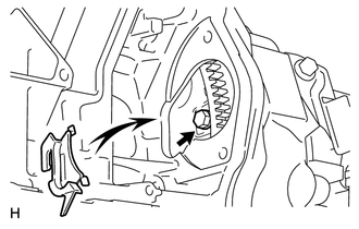
(b) Install the flywheel housing side cover.
11. INSTALL STARTER ASSEMBLY
(a) Install the starter assembly (See page .gif) ).
).
12. CONNECT NO. 1 OIL COOLER INLET TUBE AND NO. 1 OIL COOLER OUTLET TUBE
(a) Temporarily install the ends of the oil cooler inlet tube and outlet tub to each oil cooler tube union by hand.
(b) Close the 2 No. 2 flexible hose clamps and install the 2 bolts.
Torque:
5.5 N·m {56 kgf·cm, 49 in·lbf}
(c) Using a union nut wrench, tighten the inlet and outlet tubes.
Torque:
34 N·m {347 kgf·cm, 25 ft·lbf}
NOTICE:
Use the formula to calculate special torque values for situations where a union
nut wrench is combined with a torque wrench (See page
).
13. CONNECT TRANSMISSION CONTROL CABLE ASSEMBLY
(a) Connect the transmission control cable to the transmission control cable bracket with a new clip, and connect the cable end to the control shaft lever with the nut.
Torque:
14 N·m {143 kgf·cm, 10 ft·lbf}
14. INSTALL NO. 2 MANIFOLD STAY
(a) Install the stay with the 3 bolts.
Torque:
40 N·m {408 kgf·cm, 30 ft·lbf}
15. INSTALL MANIFOLD STAY
(a) Install the stay with the 3 bolts.
Torque:
40 N·m {408 kgf·cm, 30 ft·lbf}
16. INSTALL FRONT EXHAUST PIPE ASSEMBLY
(a) Install the front exhaust pipe assembly (See page
).
17. INSTALL PROPELLER SHAFT ASSEMBLY
(a) Install the propeller shaft assembly (See page
).
18. CONNECT CABLE TO NEGATIVE BATTERY TERMINAL
NOTICE:
When disconnecting the cable, some systems need to be initialized after the cable
is reconnected (See page ).
19. ADD AUTOMATIC TRANSMISSION FLUID
(a) Add automatic transmission fluid (See page
).
20. ADJUST SHIFT LEVER POSITION
21. INSPECT SHIFT LEVER POSITION
22. INSPECT FOR EXHAUST GAS LEAK
23. INSTALL FRONT NO. 1 FENDER APRON TO FRAME SEAL RH
24. INSTALL FRONT FENDER APRON SEAL RH
25. INSTALL REAR ENGINE UNDER COVER ASSEMBLY
26. INSTALL NO. 1 ENGINE UNDER COVER
27. PERFORM RESET MEMORY
(a) Perform the RESET MEMORY procedures (A/T initialization) (See page
).
 Removal
REMOVAL
PROCEDURE
1. DISCONNECT CABLE FROM NEGATIVE BATTERY TERMINAL
NOTICE:
When disconnecting the cable, some systems need to be initialized after the cable
is reconnected (See page ).
2. RE ...

Other materials about Toyota 4Runner:
Rear Occupant Classification Sensor LH Collision Detection (B1787)
DESCRIPTION
DTC B1787 is stored when the occupant classification ECU receives a collision
detection signal, which is sent by the rear occupant classification sensor LH when
an accident occurs.
DTC B1787 is also stored when the separate type front seat cu ...
Front Brake Flexible Hose
Components
COMPONENTS
ILLUSTRATION
Removal
REMOVAL
CAUTION / NOTICE / HINT
HINT:
Use the same procedure for the RH and LH sides.
The procedure listed below is for the LH side.
PROCEDURE
1. REMOVE FRONT WHEEL
2. DRAIN BRAKE FLU ...
0.0101