Toyota 4Runner: Light Control Rheostat
Components
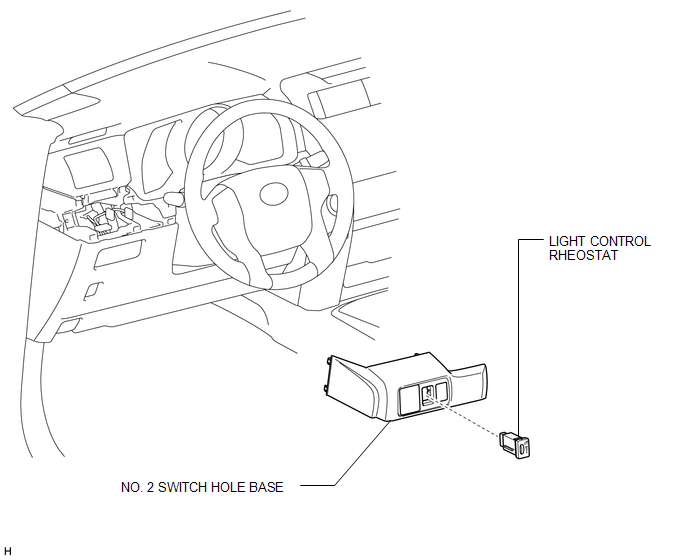
COMPONENTS
ILLUSTRATION
Inspection
INSPECTION
PROCEDURE
1. INSPECT LIGHT CONTROL RHEOSTAT (w/o TAIL Cancel Switch)
(a) Measure the resistance according to the value(s) in the table below.
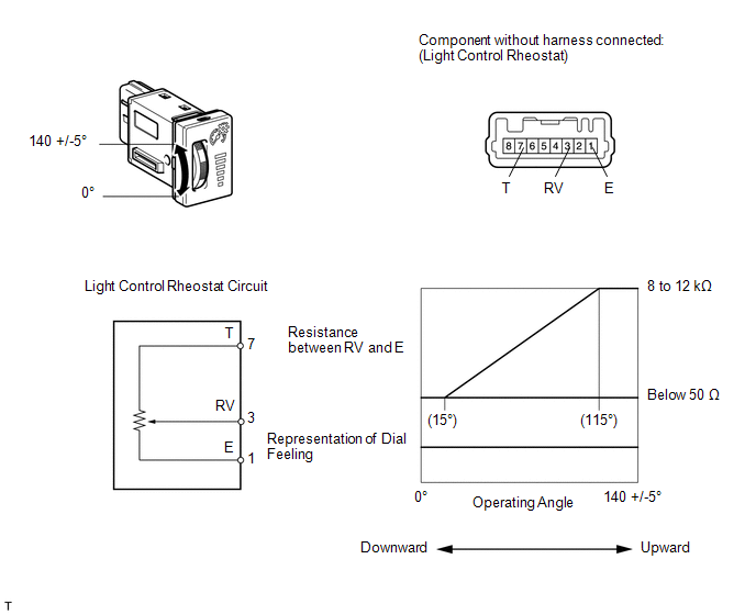
Standard Resistance:
|
Tester Connection |
Switch Condition |
Specified Condition |
|---|---|---|
|
7 (T) - 1 (E) |
Always |
8 to 12 kΩ |
|
3 (RV) - 1 (E) |
Light control rheostat fully turned upward → fully turned downward |
8 to 12 kΩ → Below 50 Ω |
If the result is not as specified, replace the rheostat.
2. INSPECT LIGHT CONTROL RHEOSTAT (w/ TAIL Cancel Switch)
(a) Measure the resistance according to the value(s) in the table below.
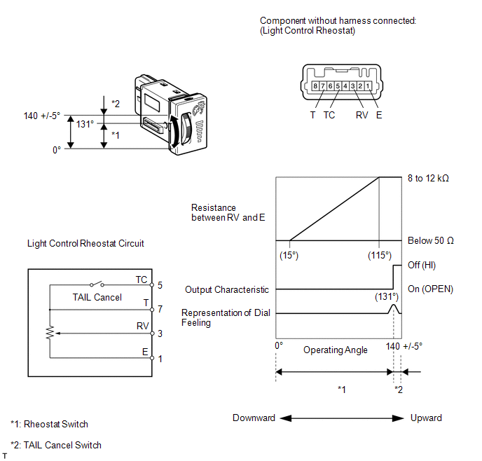
Standard Resistance:
|
Tester Connection |
Switch Condition |
Specified Condition |
|---|---|---|
|
7 (T) - 1 (E) |
Always |
8 to 12 kΩ |
|
5 (TC) - 7 (T) |
TAIL cancel switch off → on |
Below 50 Ω → 8 to 12 kΩ |
|
3 (RV) - 1 (E) |
Light control rheostat fully turned upward → fully turned downward |
8 to 12 kΩ → Below 50 Ω |
If the result is not as specified, replace the rheostat.
Installation
INSTALLATION
PROCEDURE
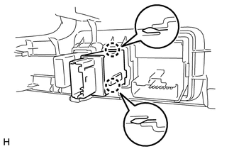
1. INSTALL LIGHT CONTROL RHEOSTAT
(a) Attach the 2 claws to install the rheostat.
2. INSTALL NO. 2 SWITCH HOLE BASE
.gif)
Removal
REMOVAL
PROCEDURE
1. REMOVE NO. 2 SWITCH HOLE BASE
.gif)
2. REMOVE LIGHT CONTROL RHEOSTAT
|
(a) Detach the 2 claws and remove the rheostat. |
|
 Combination Meter
Components
COMPONENTS
ILLUSTRATION
ILLUSTRATION
ILLUSTRATION
Removal
REMOVAL
PROCEDURE
1. DISCONNECT CABLE FROM NEGATIVE BATTERY TERMINAL
CAUTION:
Wait at least 90 seconds after di ...

Other materials about Toyota 4Runner:
Lost Communication with ECM/PCM "A" (U0100/71,U0122/71,U0124/71,U0126/71)
DESCRIPTION
DTC Code
DTC Detection Condition
Trouble Area
U0100/71
While driving at 30 km/h (19 mph), the ECM indicates a CAN communication
stop for 3 seconds or more.
CAN communicati ...
Definition Of Terms
DEFINITION OF TERMS
Term
Definition
Monitor description
Description of what the ECM monitors and how it detects malfunctions
(monitoring purpose and its details).
Related DTCs
G ...
0.0271