Toyota 4Runner: On-vehicle Inspection
ON-VEHICLE INSPECTION
PROCEDURE
1. INSPECT VOLTAGE INVERTER ASSEMBLY
HINT:
Remove interior parts so that the voltage inverter can be seen.
|
(a) Disconnect the voltage inverter connector. |
|
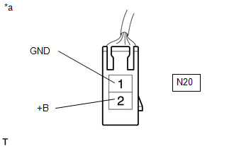
(b) Measure the voltage according to the value(s) in the table below.
Standard Voltage:
|
Tester Connection |
Switch Condition |
Specified Condition |
|---|---|---|
|
N20-1 (GND) - N20-2 (+B) |
Engine switch on (IG) |
11 to 14 V |
|
N20-1 (GND) - Body ground |
Always |
Below 1 V |
If the result is not as specified, repair or replace the harness or connector.
Text in Illustration|
*a |
Front view of wire harness connector (to Voltage Inverter Assembly) |
|
(c) Reconnect the voltage inverter connector. |
|
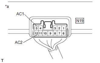
(d) Measure the voltage according to the value(s) in the table below.
Standard Voltage:
|
Tester Connection |
Switch Condition |
Specified Condition |
|---|---|---|
|
N19-5 (AC1) - N19-11 (AC2) |
Engine switch on (IG), main switch on |
AC 120 V |
If the result is not as specified, replace the voltage inverter assembly.
Text in Illustration|
*a |
Component with harness connected (Voltage Inverter Assembly) |
 Components
COMPONENTS
ILLUSTRATION
ILLUSTRATION
ILLUSTRATION
ILLUSTRATION
ILLUSTRATION
...
 Removal
REMOVAL
PROCEDURE
1. REMOVE REAR NO. 1 FLOOR STEP COVER (w/ Rear No. 2 Seat)
2. REMOVE QUARTER SCUFF PLATE RH (w/ Rear No. 2 Seat)
3. REMOVE REAR DOOR SCUFF PLATE RH
4. REMOVE REAR DOOR ...
Other materials about Toyota 4Runner:
Noise Occurs or Sound Skips when Portable Player Plays
CAUTION / NOTICE / HINT
HINT:
Perform this check with the portable player volume set at an appropriate
level.
Make sure that there are no obstructions between the portable player
and radio and display receiver assembly that may block sign ...
Removal
REMOVAL
CAUTION / NOTICE / HINT
NOTICE:
Be sure to read the precaution before performing this procedure (See page
).
HINT:
Use the same procedure for the RH and LH sides.
The procedure listed below is for the LH side.
PROCEDURE
1. RE ...
0.0067