Toyota 4Runner: Passenger Airbag ON/OFF Indicator Circuit Malfunction (B1660/43)
DESCRIPTION
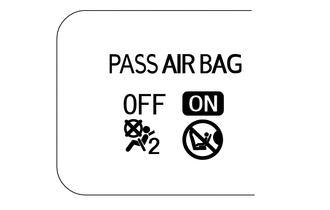
The passenger airbag ON/OFF indicator circuit consists of the airbag sensor assembly and passenger airbag ON/OFF indicator.
The passenger airbag ON/OFF indicator indicates the operation condition of the instrument panel passenger airbag, lower No. 2 instrument panel airbag, front seat side airbag RH and front seat outer belt RH.
DTC B1660/43 is stored when a malfunction is detected in the passenger airbag ON/OFF indicator circuit.
|
DTC Code |
DTC Detection Condition |
Trouble Area |
|---|---|---|
|
B1660/43 |
One of the following conditions is met:
|
|
WIRING DIAGRAM

CAUTION / NOTICE / HINT
NOTICE:
When disconnecting the cable from the negative (-) battery terminal while performing
repairs, some systems need to be initialized after the cable is reconnected (See
page .gif) ).
).
PROCEDURE
|
1. |
CHECK PASSENGER AIRBAG ON/OFF INDICATOR CONDITION |
(a) Turn the ignition switch to ON.
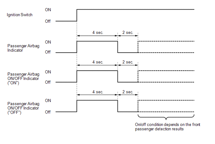
(b) Check the passenger airbag ON/OFF indicator and passenger airbag indicator operation.
HINT:
Refer to the normal condition of the passenger airbag ON/OFF indicator (See page
).
Result
|
Result |
Proceed to |
|---|---|
|
Always on |
A |
|
Off |
B |
| B | .gif) |
GO TO STEP 7 |
|
.gif)
|
2. |
CHECK CONNECTION OF CONNECTORS |
(a) Turn the ignition switch off.
(b) Disconnect the cable from the negative (-) battery terminal, and wait for at least 90 seconds.
(c) Check that the connectors are properly connected to the airbag sensor assembly and telltale light assembly.
OK:
The connectors are properly connected.
| NG | |
CONNECT CONNECTORS PROPERLY |
|
|
3. |
CHECK CONNECTORS |
(a) Disconnect the connectors from the airbag sensor assembly and telltale light assembly.
|
(b) Check that the connectors (on the airbag sensor assembly side and telltale light assembly side) are not damaged. OK: The connectors are not deformed or damaged. Text in Illustration
|
|
| NG | |
REPLACE INSTRUMENT PANEL WIRE |
|
|
4. |
CHECK PASSENGER AIRBAG ON/OFF INDICATOR |
|
(a) Connect the connector to the telltale light assembly. |
|
(b) Connect the cable to the negative (-) battery terminal, and wait for at least 2 seconds.
(c) Turn the ignition switch to ON.
(d) Check the passenger airbag ON/OFF indicator and passenger airbag indicator operation.
OK:
The passenger airbag ON/OFF indicator and passenger airbag indicator does not come on.
| NG | |
GO TO STEP 6 |
|
|
5. |
CHECK AIRBAG SENSOR ASSEMBLY |
|
(a) Turn the ignition switch off. |
|
(b) Disconnect the cable from the negative (-) battery terminal, and wait for at least 90 seconds.
(c) Connect the connector to the airbag sensor assembly.
(d) Connect the cable to the negative (-) battery terminal, and wait for at least 2 seconds.
(e) Turn the ignition switch to ON, and wait for at least 60 seconds.
(f) Clear the DTCs (See page ).
(g) Turn the ignition switch off.
(h) Turn the ignition switch to ON, and wait for at least 60 seconds.
(i) Check for DTCs (See page ).
OK:
DTC B1660 is not output.
HINT:
Codes other than DTC B1660 may be output at this time, but they are not related to this check.
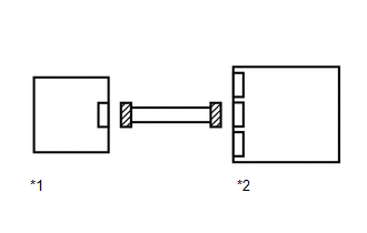
Text in Illustration|
*1 |
Telltale Light Assembly |
|
*2 |
Airbag Sensor Assembly |
| OK | |
USE SIMULATION METHOD TO CHECK |
| NG | |
REPLACE AIRBAG SENSOR ASSEMBLY |
|
6. |
CHECK INSTRUMENT PANEL WIRE (AIRBAG SENSOR - TELLTALE LIGHT) |
(a) Turn the ignition switch off.
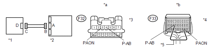 Text in Illustration
|
*1 |
Telltale Light Assembly |
*2 |
Airbag Sensor Assembly |
|
*3 |
Connector C |
*4 |
Connector B |
|
*5 |
Service Wire |
- |
- |
|
*a |
Front view of wire harness connector (to Telltale Light Assembly) |
*b |
Rear view of wire harness connector (to Airbag Sensor Assembly) |
(b) Disconnect the cable from the negative (-) battery terminal, and wait for at least 90 seconds.
(c) Disconnect the connectors from the airbag sensor assembly and telltale light assembly.
(d) Connect the cable to the negative (-) battery terminal, and wait for at least 2 seconds.
(e) Measure the voltage according to the value(s) in the table below.
Standard Voltage:
|
Tester Connection |
Switch Condition |
Specified Condition |
|---|---|---|
|
F32-3 (PAON) - Body ground |
Ignition switch ON |
Below 1 V |
|
F32-4 (P-AB) - Body ground |
Ignition switch ON |
Below 1 V |
(f) Turn the ignition switch off.
(g) Disconnect the cable from the negative (-) battery terminal, and wait for at least 90 seconds.
(h) Using a service wire, connect terminals 23 (PAON) and 17 (P-AB) of connector B.
NOTICE:
Do not forcibly insert the service wire into the terminals of the connector when connecting a service wire.
(i) Measure the resistance according to the value(s) in the table below.
Standard Resistance:
|
Tester Connection |
Condition |
Specified Condition |
|---|---|---|
|
F32-3 (PAON) - F32-4 (P-AB) |
Always |
Below 1 Ω |
(j) Disconnect the service wire from connector B.
(k) Measure the resistance according to the value(s) in the table below.
Standard Resistance:
|
Tester Connection |
Condition |
Specified Condition |
|---|---|---|
|
F32-3 (PAON) - F32-4 (P-AB) |
Always |
1 MΩ or higher |
|
F32-3 (PAON) - Body ground |
Always |
1 MΩ or higher |
|
F32-4 (P-AB) - Body ground |
Always |
1 MΩ or higher |
| OK | |
REPLACE TELLTALE LIGHT ASSEMBLY |
| NG | |
REPLACE INSTRUMENT PANEL WIRE |
|
7. |
CHECK CONNECTION OF CONNECTORS |
(a) Turn the ignition switch off.
(b) Disconnect the cable from the negative (-) battery terminal, and wait for at least 90 seconds.
(c) Check that the connectors are properly connected to the airbag sensor assembly and telltale light assembly.
OK:
The connectors are properly connected.
| NG | |
CONNECT CONNECTORS PROPERLY |
|
|
8. |
CHECK CONNECTORS |
(a) Disconnect the connectors from the airbag sensor assembly and telltale light assembly.
|
(b) Check that the connectors (on the airbag sensor assembly side and telltale light assembly side) are not damaged. OK: The connectors are not deformed or damaged. Text in Illustration
|
|
| NG | |
REPLACE INSTRUMENT PANEL WIRE |
|
|
9. |
CHECK INSTRUMENT PANEL WIRE (AIRBAG SENSOR - TELLTALE LIGHT) |
(a) Connect the cable to the negative (-) battery terminal, and wait for at least 2 seconds.
Text in Illustration
|
*1 |
Telltale Light Assembly |
*2 |
Airbag Sensor Assembly |
|
*3 |
Connector C |
*4 |
Connector B |
|
*5 |
Service Wire |
- |
- |
|
*a |
Front view of wire harness connector (to Telltale Light Assembly) |
*b |
Rear view of wire harness connector (to Airbag Sensor Assembly) |
(b) Measure the voltage according to the value(s) in the table below.
Standard Voltage:
|
Tester Connection |
Switch Condition |
Specified Condition |
|---|---|---|
|
F32-3 (PAON) - Body ground |
Ignition switch ON |
Below 1 V |
|
F32-4 (P-AB) - Body ground |
Ignition switch ON |
Below 1 V |
(c) Turn the ignition switch off.
(d) Disconnect the cable from the negative (-) battery terminal, and wait for at least 90 seconds.
(e) Using a service wire, connect terminals 23 (PAON) and 17 (P-AB) of connector B.
NOTICE:
Do not forcibly insert the service wire into the terminals of the connector when connecting a service wire.
(f) Measure the resistance according to the value(s) in the table below.
Standard Resistance:
|
Tester Connection |
Condition |
Specified Condition |
|---|---|---|
|
F32-3 (PAON) - F32-4 (P-AB) |
Always |
Below 1 Ω |
(g) Disconnect the service wire from connector B.
(h) Measure the resistance according to the value(s) in the table below.
Standard Resistance:
|
Tester Connection |
Condition |
Specified Condition |
|---|---|---|
|
F32-3 (PAON) - F32-4 (P-AB) |
Always |
1 MΩ or higher |
|
F32-3 (PAON) - Body ground |
Always |
1 MΩ or higher |
|
F32-4 (P-AB) - Body ground |
Always |
1 MΩ or higher |
| NG | |
REPLACE INSTRUMENT PANEL WIRE |
|
|
10. |
CHECK PASSENGER AIRBAG ON/OFF INDICATOR (SOURCE VOLTAGE) |
|
(a) Turn the ignition switch off. |
|
(b) Connect the connectors to the airbag sensor assembly.
(c) Connect the cable to the negative (-) battery terminal, and wait for at least 2 seconds.
(d) Measure the voltage according to the value(s) in the table below.
Standard Voltage:
|
Tester Connection |
Switch Condition |
Specified Condition |
|---|---|---|
|
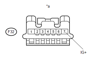
F32-7 (IG+) - Body ground |
Ignition switch ON |
11 to 14 V |
|
*a |
Front view of wire harness connector (to Telltale Light Assembly) |
| NG | |
REPLACE HARNESS AND CONNECTOR (TELLTALE LIGHT - BATTERY) OR BATTERY |
|
|
11. |
CHECK PASSENGER AIRBAG ON/OFF INDICATOR |
|
(a) Turn the ignition switch off. |
|
(b) Disconnect the cable from the negative (-) battery terminal, and wait for at least 90 seconds.
(c) Connect the connector to the telltale light assembly.
(d) Disconnect the connectors from the airbag sensor assembly.
(e) Connect the cable to the negative (-) battery terminal, and wait for at least 2 seconds.
(f) Check the indicator according to the value(s) in the table below.
OK:
|
Tester Connection |
Switch Condition |
Passenger airbag ON/OFF indicator |
|---|---|---|
|
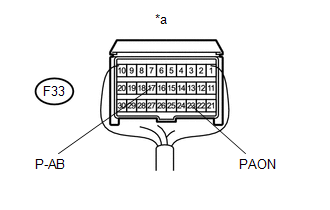
F33-23 (PAON) - Body ground |
Ignition switch ON |
"ON" comes on |
|
F33-17 (P-AB) - Body ground |
Ignition switch ON |
"OFF" comes on |
|
*a |
Rear view of wire harness connector (to Airbag Sensor Assembly) |
| NG | |
REPLACE TELLTALE LIGHT ASSEMBLY |
|
|
12. |
CHECK AIRBAG SENSOR ASSEMBLY |
|
(a) Turn the ignition switch off. |
|
(b) Disconnect the cable from the negative (-) battery terminal, and wait for at least 90 seconds.
(c) Connect the connectors to the airbag sensor assembly.
(d) Connect the cable to the negative (-) battery terminal, and wait for at least 2 seconds.
(e) Turn the ignition switch to ON, and wait for at least 60 seconds.
(f) Clear the DTCs (See page ).
(g) Turn the ignition switch off.
(h) Turn the ignition switch to ON, and wait for at least 60 seconds.
(i) Check for DTCs (See page ).
OK:
DTC B1660 is not output.
HINT:
Codes other than DTC B1660 may be output at this time, but they are not related to this check.
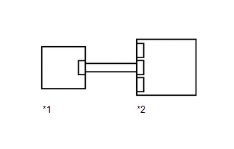
Text in Illustration|
*1 |
Telltale Light Assembly |
|
*2 |
Airbag Sensor Assembly |
| OK | |
USE SIMULATION METHOD TO CHECK |
| NG | |
REPLACE AIRBAG SENSOR ASSEMBLY |
 Front Airbag Sensor RH Malfunction (B1610/13)
DESCRIPTION
The front airbag sensor RH consists of the diagnostic circuit and frontal deceleration
sensor, etc.
If the center airbag sensor receives signals from the frontal deceleration sensor,
...
 SRS Warning Light Remains ON
DESCRIPTION
The SRS warning light is located in the combination meter.
When the SRS is normal, the SRS warning light comes on for approximately 6 seconds
after the ignition switch is turned from o ...
Other materials about Toyota 4Runner:
Door Courtesy Light(for Rear Door)
Components
COMPONENTS
ILLUSTRATION
Removal
REMOVAL
CAUTION / NOTICE / HINT
HINT:
Use the same procedure for the RH and LH sides.
The procedure listed below is for the LH side.
PROCEDURE
1. REMOVE REAR DOOR INSIDE HANDLE BEZEL L ...
Park / Neutral Position Switch Circuit
DESCRIPTION
This circuit sends the park/neutral position switch assembly signals to the clearance
warning ECU assembly.
WIRING DIAGRAM
CAUTION / NOTICE / HINT
NOTICE:
Inspect the fuses for circuits related to this system before performing the followin ...
0.0067