Toyota 4Runner: Power Seat Position is not Memorized
DESCRIPTION
When the seat memory SET switch and a memory switch (M1 or M2) are pressed simultaneously, the main body ECU commands the position control ECU through CAN communication to record the value of each position sensor.
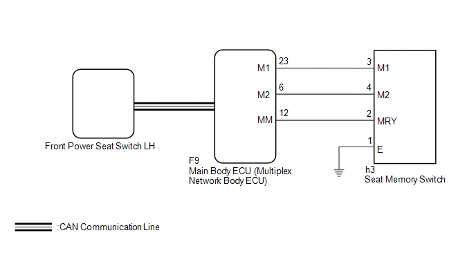
WIRING DIAGRAM
CAUTION / NOTICE / HINT
NOTICE:
The front power seat control system (w/ Memory) uses the CAN communication system.
First, confirm that there are no malfunctions in the communication system by checking
the communication function of the CAN communication system (See page
.gif) ).
).
PROCEDURE
|
1. |
CHECK FRONT POWER SEAT CONTROL FUNCTION |
(a) Check that each function of the power seat operates normally by using the
front power seat switches (See page ).
OK:
Each function of power seat operates normally by using seat switches.
| NG | .gif) |
GO TO PROBLEM SYMPTOMS TABLE |
|
.gif)
|
2. |
READ VALUE USING TECHSTREAM (SEAT POSITION MEMORY) |
(a) Use the seat memory switch to record the seat position (See page
).
NOTICE:
- The seat position will not be recorded if the SET switch and both memory switches are pressed simultaneously.
- If a memorizing operation has failed, release all switches. The seat memory function does not operate unless the switches are released.
(b) Using the Techstream, read the Data List (See page
).
Driver Seat
|
Tester Display |
Measurement Item/Range |
Normal Condition |
Diagnostic Note |
|---|---|---|---|
|
Seat Memory No1 |
Seat position memorized with M1 switch / Mem or Not Mem |
Mem: Memorized Not Mem: Not memorized |
- |
|
Seat Memory No2 |
Seat position memorized with M2 switch / Mem or Not Mem |
Mem: Memorized Not Mem: Not memorized |
- |
OK:
"Mem" is displayed on the tester.
| OK | |
END (USE SIMULATION METHOD TO CHECK) |
|
|
3. |
INSPECT SEAT MEMORY SWITCH |
(a) Remove the seat memory switch (See page
).
(b) Inspect the seat memory switch (See page
).
| NG | |
REPLACE SEAT MEMORY SWITCH |
|
|
4. |
CHECK HARNESS AND CONNECTOR (MAIN BODY ECU (MULTIPLEX NETWORK BODY ECU) - SEAT MEMORY SWITCH) |
(a) Disconnect the F9 main body ECU (multiplex network body ECU) connector.
(b) Disconnect the h3 seat memory switch connector.
(c) Measure the resistance according to the value(s) in the table below.
Standard Resistance:
|
Tester Connection |
Condition |
Specified Condition |
|---|---|---|
|
F9-23 (M1) - h3-3 (M1) |
Always |
Below 1 Ω |
|
F9-6 (M2) - h3-4 (M2) |
Always |
Below 1 Ω |
|
F9-12 (MM) - h3-2 (MRY) |
Always |
Below 1 Ω |
|
F9-23 (M1) - Body ground |
Always |
10 kΩ or higher |
|
F9-6 (M2) - Body ground |
Always |
10 kΩ or higher |
|
F9-12 (MM) - Body ground |
Always |
10 kΩ or higher |
| NG | |
REPAIR OR REPLACE HARNESS OR CONNECTOR |
|
|
5. |
REPLACE FRONT POWER SEAT SWITCH LH |
(a) Replace the front power seat switch LH (See page
).
(b) Perform the memory operation (See page ).
OK:
Memory operation is normally.
| OK | |
END (FRONT POWER SEAT SWITCH LH WAS DEFECTIVE) |
| NG | |
REPLACE MAIN BODY ECU (MULTIPLEX NETWORK BODY ECU) |
 Front Power Seat does not Operate with Front Power Seat Switch
DESCRIPTION
When a signal is input into the front power seat switch LH (position control
ECU), the ECU manages the signals received from the front power seat switch LH and
operates each motor. Wh ...

Other materials about Toyota 4Runner:
Accumulator Solenoid Malfunction / Upside (C1831/31,C1832/32)
DESCRIPTION
The stabilizer control ECU receives information from the steering angle sensor,
skid control ECU (speed signal) and yaw rate and acceleration sensor via CAN communication.
Based on this information, the stabilizer control ECU turns the stabili ...
Removal
REMOVAL
PROCEDURE
1. REMOVE INSTRUMENT PANEL SUB-ASSEMBLY
(a) Remove the instrument panel sub-assembly (See page
).
2. REMOVE NO. 2 INSTRUMENT PANEL WIRE
(a) Detach the clamp.
(b) Disconnect the 2 co ...
0.0256