Toyota 4Runner: Front Power Seat does not Operate with Front Power Seat Switch
DESCRIPTION
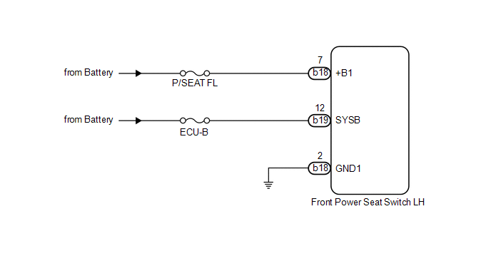
When a signal is input into the front power seat switch LH (position control ECU), the ECU manages the signals received from the front power seat switch LH and operates each motor. When 2 or more signals are input, the motors only operate when the signals are from the slide switch and reclining switch.
WIRING DIAGRAM
CAUTION / NOTICE / HINT
NOTICE:
Inspect the fuses for circuits related to this system before performing the following inspection procedure.
PROCEDURE
|
1. |
CHECK HARNESS AND CONNECTOR (FRONT POWER SEAT SWITCH LH - BATTERY AND BODY GROUND) |
|
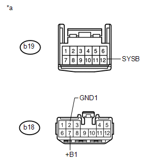
(a) Disconnect the b18 and b19 front power seat switch LH connectors. |
|
(b) Measure the voltage according to the value(s) in the table below.
Standard Voltage:
|
Tester Connection |
Condition |
Specified Condition |
|---|---|---|
|
b18-7 (+B1) - Body ground |
Always |
11 to 14 V |
|
b19-12 (SYSB) - Body ground |
Always |
11 to 14 V |
(c) Measure the resistance according to the value(s) in the table below.
Standard Resistance:
|
Tester Connection |
Condition |
Specified Condition |
|---|---|---|
|
b18-2 (GND1) - Body ground |
Always |
Below 1 Ω |
|
*a |
Front view of wire harness connector (to Front Power Seat Switch LH) |
| OK | .gif) |
REPLACE FRONT POWER SEAT SWITCH LH |
| NG | |
REPAIR OR REPLACE HARNESS OR CONNECTOR |
 Slide Sensor Malfunction (B2650)
DESCRIPTION
When the front power seat switch LH does not receive a sensor signal despite
forward or backward movement of the seat by power seat motor operation, this DTC
is stored.
DT ...
 Power Seat Position is not Memorized
DESCRIPTION
When the seat memory SET switch and a memory switch (M1 or M2) are pressed simultaneously,
the main body ECU commands the position control ECU through CAN communication to
record the ...
Other materials about Toyota 4Runner:
Using the hands-free phone system for the first time
Before using the hands-free phone system, it is necessary to register a
cellular phone in the system. The phone registration mode will be entered
automatically when starting the system with no cellular phone registered. Follow
the procedure below to regi ...
System Diagram
SYSTEM DIAGRAM
Transmitting ECU
(Transmitter)
Receiving ECU
Signal
Communication Method
Center Airbag Sensor
ECM
Crash detection signal
Fuel cut signa ...
0.0107