Toyota 4Runner: Power Supply Voltage Malfunction (C1882/82)
DESCRIPTION
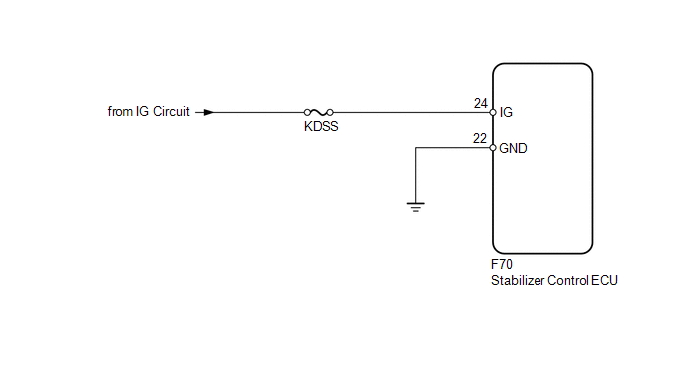
The stabilizer control ECU recognizes the ignition switch ON signal based on the voltage input to the IG terminal.
|
DTC Code |
DTC Detection Condition |
Trouble Area |
|---|---|---|
|
C1882/82 |
The IG terminal voltage is 10 V or less or 16 V or higher for 0.5 seconds. |
|
WIRING DIAGRAM
CAUTION / NOTICE / HINT
NOTICE:
Inspect the fuses for circuits related to this system before performing the following inspection procedure.
PROCEDURE
|
1. |
READ VALUE USING TECHSTREAM (IG POWER SOURCE VOLTAGE) |
(a) Turn the ignition switch off.
(b) Connect the Techstream to the DLC3.
(c) Turn the ignition switch to ON.
(d) Turn the Techstream on.
(e) Enter the following menus: Chassis / KDSS / Data List.
(f) Select the item below in the Data List, and read the value displayed on the Techstream.
KDSS|
Tester Display |
Measurement Item/Range |
Normal Condition |
Diagnostic Note |
|---|---|---|---|
|
IG Power Source Voltage |
IG Power Source Voltage/ Min.: 0.0 V Max.: 25.5 V |
Ignition switch ON: 11 to 14 V |
- |
Standard voltage:
11 to 14 V
| NG | .gif) |
GO TO STEP 3 |
|
.gif)
|
2. |
RECONFIRM DTC |
(a) Clear the DTCs (See page .gif) ).
).
(b) Check for DTCs (See page ).
Result
|
Result |
Proceed to |
|---|---|
|
DTC is output |
A |
|
DTC is not output |
B |
| A | |
REPLACE STABILIZER CONTROL ECU |
| B | |
USE SIMULATION METHOD TO CHECK |
|
3. |
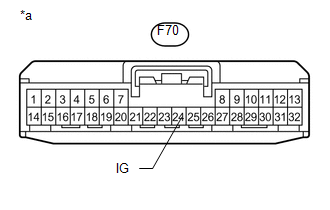
CHECK HARNESS AND CONNECTOR (IG TERMINAL) |
(a) Disconnect the stabilizer control ECU connector.
|
(b) Measure the voltage according to the value(s) in the table below. Standard Voltage:
|
|
| NG | |
REPAIR OR REPLACE HARNESS OR CONNECTOR |
|
|
4. |
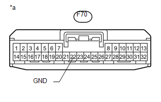
CHECK HARNESS AND CONNECTOR (GND TERMINAL) |
(a) Disconnect the stabilizer control ECU connector.
|
(b) Measure the resistance according to the value(s) in the table below. Standard Resistance:
|
|
| OK | |
REPLACE STABILIZER CONTROL ECU |
| NG | |
REPAIR OR REPLACE HARNESS OR CONNECTOR |
 On-vehicle Inspection
ON-VEHICLE INSPECTION
PROCEDURE
1. INSPECT INDICATOR LIGHT
(a) Check that the KDSS indicator light comes on for 2 seconds when the ignition
switch is turned to ON.
If the indicator check result ...
 Speed Sensor Circuit Malfunction (C1883/83)
DESCRIPTION
The stabilizer control ECU receives the speed signal from the skid control ECU
via CAN communication.
DTC Code
DTC Detection Condition
Trouble Area
...
Other materials about Toyota 4Runner:
Data List / Active Test
DATA LIST / ACTIVE TEST
1. READ DATA LIST
HINT:
Using the Techstream to read the Data List allows the values or states of switches,
sensors, actuators and other items to be read without removing any parts. This non-intrusive
inspection can be very usefu ...
Terminals Of Ecu
TERMINALS OF ECU
1. CHECK OCCUPANT CLASSIFICATION ECU
Terminal No. (Symbol)
Wiring Color
Terminal Description
Condition
Specified Condition
a9-1 (+B) - a9-3 (GND)
W - W-B
...
0.0068