Toyota 4Runner: Terminals Of Ecu
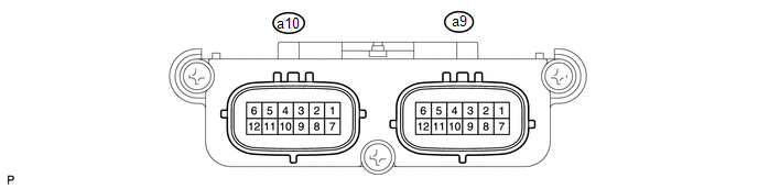
TERMINALS OF ECU
1. CHECK OCCUPANT CLASSIFICATION ECU
|
Terminal No. (Symbol) |
Wiring Color |
Terminal Description |
Condition |
Specified Condition |
|---|---|---|---|---|
|
a9-1 (+B) - a9-3 (GND) |
W - W-B |
Battery power supply |
Always |
11 to 14 V |
|
a9-2 (DIA) - a9-3 (GND) |
GR - W-B |
Diagnosis (DLC3) |
Ignition switch ON |
Pulse generation |
|
a9-3 (GND) - Body ground |
W-B - Body ground |
Ground |
Always |
Below 1 V |
|
a9-4 (FSR-) - a9-3 (GND) |
LG - W-B |
Center airbag sensor assembly communication line |
Always |
Below 1 V |
|
a9-5 (BGND) - a9-3 (GND) |
P - W-B |
Front passenger side buckle switch ground line |
Always |
Below 1 V |
|
a9-7 (IG2) - a9-3 (GND) |
B - W-B |
Ignition switch power supply |
Ignition switch ON |
11 to 14 V |
|
a9-8 (FSR+) - a9-4 (FSR- ) |
L - LG |
Center airbag sensor assembly communication line |
Ignition switch ON |
Pulse generation |
|
a9-9 (BSW) - a9-5 (BGND) |
G - P |
Front passenger side buckle switch line |
Always |
Pulse generation |
|
a10-1 (SGD1) - a9-3 (GND) |
G - W-B |
Front occupant classification sensor LH ground line |
Always |
Below 1 V |
|
a10-2 (SGD2) - a9-3 (GND) |
LG - W-B |
Front occupant classification sensor RH ground line |
Always |
Below 1 V |
|
a10-3 (SGD3) - a9-3 (GND) |
W - W-B |
Rear occupant classification sensor LH ground line |
Always |
Below 1 V |
|
a10-4 (SGD4) - a9-3 (GND) |
BR - W-B |
Rear occupant classification sensor RH ground line |
Always |
Below 1 V |
|
a10-11 (SVC1) - a10-1 (SGD1) |
R - G |
Front occupant classification sensor LH power supply line |
Ignition switch ON, load applied to front occupant classification sensor LH |
4.9 to 5.1 V |
|
a10-12 (SVC2) - a10-2 (SGD2) |
W - LG |
Front occupant classification sensor RH power supply line |
Ignition switch ON, load applied to front occupant classification sensor RH |
4.9 to 5.1 V |
|
a10-5 (SVC3) - a10-3 (SGD3) |
GR - W |
Rear occupant classification sensor LH signal line |
Ignition switch ON, load applied to rear occupant classification sensor LH |
4.9 to 5.1 V |
|
a10-6 (SVC4) - a10-4 (SGD4) |
V - BR |
Rear occupant classification sensor RH signal line |
Ignition switch ON, load applied to rear occupant classification sensor RH |
4.9 to 5.1 V |
|
a10-7 (SIG1) - a10-1 (SGD1) |
P - G |
Front occupant classification sensor LH signal line |
Ignition switch ON, load applied to front occupant classification sensor LH |
0 to 5.1 V |
|
a10-8 (SIG2) - a10-2 (SGD2) |
L - LG |
Front occupant classification sensor RH signal line |
Ignition switch ON, load applied to front occupant classification sensor RH |
0 to 5.1 V |
|
a10-9 (SIG3) - a10-3 (SGD3) |
SB - W |
Rear occupant classification sensor LH power supply line |
Ignition switch ON, load applied to rear occupant classification sensor LH |
0 to 5.1 V |
|
a10-10 (SIG4) - a10-4 (SGD4) |
B - BR |
Rear occupant classification sensor RH power supply line |
Ignition switch ON, load applied to rear occupant classification sensor RH |
0 to 5.1 V |
 Problem Symptoms Table
PROBLEM SYMPTOMS TABLE
HINT:
Use the table below to help determine the cause of problem symptoms.
If multiple suspected areas are listed, the potential causes of the symptoms
are lis ...
 Data List / Active Test
DATA LIST / ACTIVE TEST
NOTICE:
In the table below, the values listed under "Normal Condition" are reference
values. Do not depend solely on these reference values when deciding whether ...
Other materials about Toyota 4Runner:
Adjustment
ADJUSTMENT
CAUTION / NOTICE / HINT
NOTICE:
This transmission requires Toyota Genuine ATF WS.
After servicing the transmission, you must follow the ATF adjustment
procedure.
Maintain the vehicle in a horizontal position while adjusting ...
System Diagram
SYSTEM DIAGRAM
Communication Table
Sender
Receiver
Signal
Line
Center airbag sensor assembly
Main body ECU (multiplex network body ECU)
Front seat inner belt LH buckle swit ...
0.0213