Toyota 4Runner: Power Window Switch Malfunction (B2312)
DESCRIPTION
The power window regulator motor is driven by operating the power window regulator switch. The power window regulator motor assembly consists of the motor and ECU.
This DTC is output when the ECU built into the regulator motor and master switch determines that the multiplex network master switch assembly or power window regulator switch assembly is stuck.
HINT:
This DTC may be stored for all the windows.
NOTICE:
- When a power window regulator is reinstalled or replaced, the power window control system must be initialized.
- After any door glass or a door glass run has been replaced, the jam
protection function may operate unexpectedly when the auto up function is
used. In such cases, the auto up function can be resumed by repeating the
following operation at least 5 times:
- Close the power window by fully pulling up the power window switch and holding it in the auto up position.
- Open the power window by fully pushing down the power window switch.
|
DTC Code |
DTC Detection Condition |
Trouble Area |
|---|---|---|
|
B2312 |
Either condition is met:
|
Multiplex network master switch |
|
DTC Code |
DTC Detection Condition |
Trouble Area |
|---|---|---|
|
B2312 |
Either condition is met:
|
|
|
DTC Code |
DTC Detection Condition |
Trouble Area |
|---|---|---|
|
B2312 |
Either condition is met:
|
|
|
DTC Code |
DTC Detection Condition |
Trouble Area |
|---|---|---|
|
B2312 |
Either condition is met:
|
|
|
DTC Code |
DTC Detection Condition |
Trouble Area |
|---|---|---|
|
B2312 |
Either condition is met:
|
|
WIRING DIAGRAM
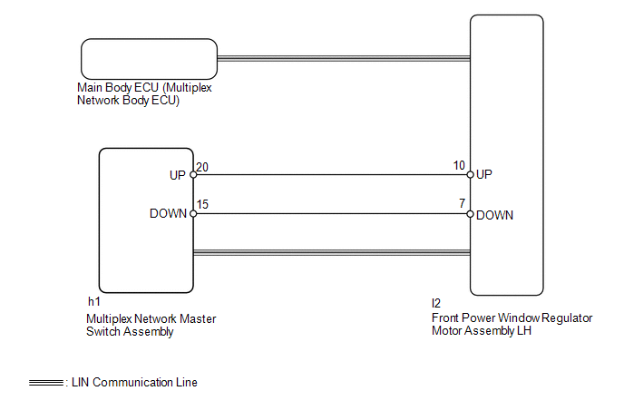
1. for Front LH:
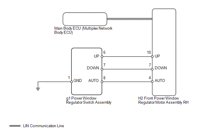
2. for Front RH:
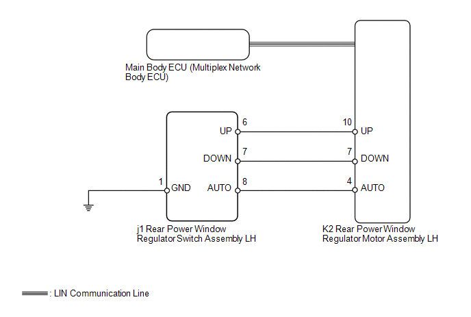
3. for Rear LH:
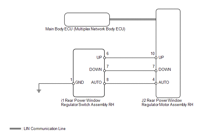
4. for Rear RH:
CAUTION / NOTICE / HINT
HINT:
Since the power window control system has functions that use LIN communication, first confirm that there is no malfunction in the communication system by inspecting the LIN communication functions in accordance with the "How to Proceed with Troubleshooting" procedures. Then, conduct the following inspection procedure.
PROCEDURE
|
1. |
CHECK FOR DTC |
(a) Clear the DTC (See page .gif) ).
).
(b) Check for DTCs (See page ).
Result
|
Result |
Proceed to |
|---|---|
|
No DTCs output |
A |
|
LIN communication DTCs are output |
B |
|
DTC B2312 is output |
C |
| A | .gif) |
END (DTC WAS STORED DUE TO SWITCH BEING OPERATED FOR 20 SECONDS OR MORE) |
| B | |
GO TO LIN COMMUNICATION SYSTEM |
|
.gif)
|
2. |
CHECK DTC OUTPUT |
(a) Check the parts which the DTCs have been output from.
Result|
Result |
Proceed to |
|---|---|
|
DTC output from multiplex network master switch |
A |
|
DTC output from front power window regulator motor LH |
B |
|
DTC output from front power window regulator motor RH |
C |
|
DTC output from rear power window regulator motor LH |
D |
|
DTC output from rear power window regulator motor RH |
E |
| A | |
REPLACE MULTIPLEX NETWORK MASTER SWITCH ASSEMBLY |
| C | |
GO TO STEP 5 |
| D | |
GO TO STEP 8 |
| E | |
GO TO STEP 11 |
|
|
3. |
READ VALUE USING TECHSTREAM (MULTIPLEX NETWORK MASTER SWITCH) |
(a) Use the Data List to check if the power window regulator motor is functioning
properly (See page ).
D-Door Motor
|
Tester Display |
Measurement Item/Range |
Normal Condition |
Diagnostic Note |
|---|---|---|---|
|
D Door P/W Up SW |
Driver side power window manual up signal / ON or OFF |
ON: Driver side power window manual up switch operated OFF: Driver side power window switch not operated |
- |
|
D Door P/W Down SW |
Driver side power window manual down signal / ON or OFF |
ON: Driver side power window manual down switch operated OFF: Driver side power window switch not operated |
- |
OK:
On tester screen, each item changes between ON and OFF according to above chart.
| OK | |
REPLACE FRONT POWER WINDOW REGULATOR MOTOR ASSEMBLY LH |
|
|
4. |
CHECK HARNESS AND CONNECTOR (MULTIPLEX NETWORK MASTER SWITCH - FRONT POWER WINDOW REGULATOR MOTOR ASSEMBLY LH) |
(a) Disconnect the h1 multiplex network master switch connector.
(b) Disconnect the I2 power window regulator motor connector.
(c) Measure the resistance according to the value(s) in the table below.
Standard Resistance:
|
Tester Connection |
Condition |
Specified Condition |
|---|---|---|
|
h1-20 (UP) - I2-10 (UP) |
Always |
Below 1 Ω |
|
h1-15 (DOWN) - I2-7 (DOWN) |
Always |
Below 1 Ω |
|
h1-20 (UP) - Body ground |
Always |
10 kΩ or higher |
|
h1-15 (DOWN) - Body ground |
Always |
10 kΩ or higher |
| OK | |
REPLACE FRONT POWER WINDOW REGULATOR MOTOR ASSEMBLY LH |
| NG | |
REPAIR OR REPLACE HARNESS OR CONNECTOR |
|
5. |
READ VALUE USING TECHSTREAM (POWER WINDOW REGULATOR SWITCH) |
(a) Use the Data List to check if the power window regulator motor is functioning
properly (See page ).
P-Door Motor
|
Tester Display |
Measurement Item/Range |
Normal Condition |
Diagnostic Note |
|---|---|---|---|
|
P Door P/W Auto SW |
Front passenger side power window auto up/down signal / ON or OFF |
ON: Front passenger side power window auto up/down switch operated OFF: Front passenger side power window regulator switch not operated |
- |
|
P Door P/W Up SW |
Front passenger side power window manual up signal / ON or OFF |
ON: Front passenger side power window manual up switch operated OFF: Front passenger side power window regulator switch not operated |
- |
|
P Door P/W Down SW |
Front passenger side power window manual down signal / ON or OFF |
ON: Front passenger side power window manual down switch operated OFF: Front passenger side power window regulator switch not operated |
- |
OK:
On tester screen, each item changes between ON and OFF according to above chart.
| OK | |
REPLACE FRONT POWER WINDOW REGULATOR MOTOR ASSEMBLY RH |
|
|
6. |
INSPECT POWER WINDOW REGULATOR SWITCH ASSEMBLY |
|
(a) Remove the power window regulator switch (See page
|
|
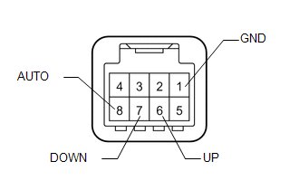
(b) Measure the resistance according to the value(s) in the table below.
Standard Resistance:
|
Tester Connection |
Switch Condition |
Specified Condition |
|---|---|---|
|
6 (UP) - 1 (GND) |
Manual up operation |
Below 1 Ω |
|
7 (DOWN) - 1 (GND) |
Manual down operation |
Below 1 Ω |
|
8 (AUTO) - 1 (GND) |
Auto up/down operation |
Below 1 Ω |
|
6 (UP) - 1 (GND) |
Not operated |
10 kΩ or higher |
|
7 (DOWN) - 1 (GND) |
Not operated |
10 kΩ or higher |
|
8 (AUTO) - 1 (GND) |
Not operated |
10 kΩ or higher |
| NG | |
REPLACE POWER WINDOW REGULATOR SWITCH ASSEMBLY |
|
|
7. |
CHECK HARNESS AND CONNECTOR (POWER WINDOW REGULATOR SWITCH ASSEMBLY - FRONT POWER WINDOW REGULATOR MOTOR ASSEMBLY RH) |
(a) Disconnect the g1 power window regulator switch connector.
(b) Disconnect the H2 power window regulator motor connector.
(c) Measure the resistance according to the value(s) in the table below.
Standard Resistance:
|
Tester Connection |
Condition |
Specified Condition |
|---|---|---|
|
g1-6 (UP) - H2-10 (UP) |
Always |
Below 1 Ω |
|
g1-7 (DOWN) - H2-7 (DOWN) |
Always |
Below 1 Ω |
|
g1-8 (AUTO) - H2-4 (AUTO) |
Always |
Below 1 Ω |
|
g1-6 (UP) - Body ground |
Always |
10 kΩ or higher |
|
g1-7 (DOWN) - Body ground |
Always |
10 kΩ or higher |
|
g1-8 (AUTO) - Body ground |
Always |
10 kΩ or higher |
| OK | |
REPLACE FRONT POWER WINDOW REGULATOR MOTOR ASSEMBLY RH |
| NG | |
REPAIR OR REPLACE HARNESS OR CONNECTOR |
|
8. |
READ VALUE USING TECHSTREAM (REAR POWER WINDOW REGULATOR SWITCH LH) |
(a) Use the Data List to check if the power window regulator motor is functioning
properly (See page ).
RL-Door Motor
|
Tester Display |
Measurement Item/Range |
Normal Condition |
Diagnostic Note |
|---|---|---|---|
|
RL Door P/W Auto SW |
Rear power window LH auto up/down signal / ON or OFF |
ON: Rear power window LH auto up/down switch operated OFF: Rear power window LH switch not operated |
- |
|
RL Door P/W Up SW |
Rear power window LH manual up signal / ON or OFF |
ON: Rear power window LH manual up switch operated OFF: Rear power window LH switch not operated |
- |
|
RL Door P/W Down SW |
Rear power window LH manual down signal / ON or OFF |
ON: Rear power window LH manual down switch operated OFF: Rear power window LH switch not operated |
- |
OK:
On tester screen, each item changes between ON and OFF according to above chart.
| OK | |
REPLACE REAR POWER WINDOW REGULATOR MOTOR ASSEMBLY LH |
|
|
9. |
INSPECT REAR POWER WINDOW REGULATOR SWITCH ASSEMBLY LH |
|
(a) Remove the rear power window regulator switch (See page
|
|
(b) Measure the resistance according to the value(s) in the table below.
Standard Resistance:
|
Tester Connection |
Switch Condition |
Specified Condition |
|---|---|---|
|
6 (UP) - 1 (GND) |
Manual up operation |
Below 1 Ω |
|
7 (DOWN) - 1 (GND) |
Manual down operation |
Below 1 Ω |
|
8 (AUTO) - 1 (GND) |
Auto up/down operation |
Below 1 Ω |
|
6 (UP) - 1 (GND) |
Not operated |
10 kΩ or higher |
|
7 (DOWN) - 1 (GND) |
Not operated |
10 kΩ or higher |
|
8 (AUTO) - 1 (GND) |
Not operated |
10 kΩ or higher |
| NG | |
REPLACE REAR POWER WINDOW REGULATOR SWITCH ASSEMBLY LH |
|
|
10. |
CHECK HARNESS AND CONNECTOR (REAR POWER WINDOW REGULATOR SWITCH ASSEMBLY LH - REAR POWER WINDOW REGULATOR MOTOR ASSEMBLY LH) |
(a) Disconnect the j1 rear power window regulator switch connector.
(b) Disconnect the K2 rear power window regulator motor connector.
(c) Measure the resistance according to the value(s) in the table below.
Standard Resistance:
|
Tester Connection |
Condition |
Specified Condition |
|---|---|---|
|
j1-6 (UP) - K2-10 (UP) |
Always |
Below 1 Ω |
|
j1-7 (DOWN) - K2-7 (DOWN) |
Always |
Below 1 Ω |
|
j1-8 (AUTO) - K2-4 (AUTO) |
Always |
Below 1 Ω |
|
j1-6 (UP) - Body ground |
Always |
10 kΩ or higher |
|
j1-7 (DOWN) - Body ground |
Always |
10 kΩ or higher |
|
j1-8 (AUTO) - Body ground |
Always |
10 kΩ or higher |
| OK | |
REPLACE REAR POWER WINDOW REGULATOR MOTOR ASSEMBLY LH |
| NG | |
REPAIR OR REPLACE HARNESS OR CONNECTOR |
|
11. |
READ VALUE USING TECHSTREAM (REAR POWER WINDOW REGULATOR SWITCH RH) |
(a) Use the Data List to check if the power window regulator motor is functioning
properly (See page ).
RR-Door Motor
|
Tester Display |
Measurement Item/Range |
Normal Condition |
Diagnostic Note |
|---|---|---|---|
|
RR Door P/W Auto SW |
Rear power window RH auto up/down signal / ON or OFF |
ON: Rear power window RH auto up/down switch operated OFF: Rear power window RH switch not operated |
- |
|
RR Door P/W Up SW |
Rear power window RH manual up signal / ON or OFF |
ON: Rear power window RH manual up switch operated OFF: Rear power window RH switch not operated |
- |
|
RR Door P/W Down SW |
Rear power window RH manual down signal / ON or OFF |
ON: Rear power window RH manual down switch operated OFF: Rear power window RH switch not operated |
- |
OK:
On tester screen, each item changes between ON and OFF according to above chart.
| OK | |
REPLACE REAR POWER WINDOW REGULATOR MOTOR ASSEMBLY RH |
|
|
12. |
INSPECT REAR POWER WINDOW REGULATOR SWITCH ASSEMBLY RH |
|
(a) Remove the rear power window regulator switch (See page
|
|
(b) Measure the resistance according to the value(s) in the table below.
Standard Resistance:
|
Tester Connection |
Switch Condition |
Specified Condition |
|---|---|---|
|
6 (UP) - 1 (GND) |
Manual up operation |
Below 1 Ω |
|
7 (DOWN) - 1 (GND) |
Manual down operation |
Below 1 Ω |
|
8 (AUTO) - 1 (GND) |
Auto up/down operation |
Below 1 Ω |
|
6 (UP) - 1 (GND) |
Not operated |
10 kΩ or higher |
|
7 (DOWN) - 1 (GND) |
Not operated |
10 kΩ or higher |
|
8 (AUTO) - 1 (GND) |
Not operated |
10 kΩ or higher |
| NG | |
REPLACE REAR POWER WINDOW REGULATOR SWITCH ASSEMBLY RH |
|
|
13. |
CHECK HARNESS AND CONNECTOR (REAR POWER WINDOW REGULATOR SWITCH ASSEMBLY RH - REAR POWER WINDOW REGULATOR MOTOR ASSEMBLY RH) |
(a) Disconnect the i1 rear power window regulator switch connector.
(b) Disconnect the J2 rear power window regulator motor connector.
(c) Measure the resistance according to the value(s) in the table below.
Standard Resistance:
|
Tester Connection |
Condition |
Specified Condition |
|---|---|---|
|
i1-6 (UP) - J2-10 (UP) |
Always |
Below 1 Ω |
|
i1-7 (DOWN) - J2-7 (DOWN) |
Always |
Below 1 Ω |
|
i1-8 (AUTO) - J2-4 (AUTO) |
Always |
Below 1 Ω |
|
i1-6 (UP) - Body ground |
Always |
10 kΩ or higher |
|
i1-7 (DOWN) - Body ground |
Always |
10 kΩ or higher |
|
i1-8 (AUTO) - Body ground |
Always |
10 kΩ or higher |
| OK | |
REPLACE REAR POWER WINDOW REGULATOR MOTOR ASSEMBLY RH |
| NG | |
REPAIR OR REPLACE HARNESS OR CONNECTOR |
 Back Door Power Window ECU Inner Motor Failure (B2311)
DESCRIPTION
The power window regulator motor is operated by the back door power window regulator
switch. The back power window regulator motor assembly has motor and ECU functions.
This DTC is sto ...
 Power Window Motor Malfunction (B2311)
DESCRIPTION
The power window regulator motor is operated by the multiplex network master
switch or power window regulator switch. The power window regulator motor assembly
has motor and ECU funct ...
Other materials about Toyota 4Runner:
Installation
INSTALLATION
PROCEDURE
1. INSTALL HOOD LOCK ASSEMBLY
(a) Apply MP grease to the sliding areas of the hood lock assembly.
(b) Connect the hood lock control cable assembly.
(c) Connect the connector.
(d) Install the hood lock assembly with the 3 ...
Removal
REMOVAL
CAUTION / NOTICE / HINT
CAUTION:
Wear protective gloves. Sharp areas on the parts may injure your hands.
HINT:
Use the same procedure for the RH and LH sides.
The procedure listed below is for the LH side.
PROCEDURE
1. REMOVE F ...
0.0069