Toyota 4Runner: Radio Broadcast cannot be Received or Poor Reception
CAUTION / NOTICE / HINT
NOTICE:
After replacing the navigation receiver assembly of vehicles subscribed to pay-type satellite radio broadcasts, XM radio ID registration is necessary.
PROCEDURE
|
1. |
CHECK NAVIGATION RECEIVER ASSEMBLY |
(a) Check the radio automatic station search function.
(1) Check the radio automatic station search function by activating it.
|
Result |
Proceed to |
|---|---|
|
Automatic station search function does not stop |
A |
|
Automatic station search function stops on a station |
B |
| B | .gif) |
USE SIMULATION METHOD TO CHECK |
|
.gif)
|
2. |
CHECK OPTIONAL COMPONENTS |
(a) Check if any optional components that may decrease reception capacity, such as sunshade film or a telephone antenna, are installed.
|
Result |
Proceed to |
|---|---|
|
Optional components are not installed |
A |
|
Optional components are installed |
B |
NOTICE:
Do not remove optional components without the permission of the customer.
| B | |
REMOVE OPTIONAL COMPONENTS AND CHECK AGAIN (SEE NOTICE ABOVE) |
|
|
3. |
CHECK NAVIGATION RECEIVER ASSEMBLY |
|
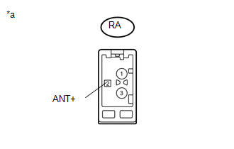
(a) Preparation for check (1) Remove the antenna connector from the navigation receiver assembly. |
|
(b) Check for noise
(1) Turn the ignition switch to ACC with the navigation receiver assembly connector connected.
(2) Turn the radio on and tune into AM mode.
(3) Place a screwdriver, thin wire or other metal object on the navigation receiver assembly antenna jack and check that noise can be heard from the speakers.
OK:
Noise can be heard from the speakers.
| NG | |
REPLACE NAVIGATION RECEIVER ASSEMBLY |
|
|
4. |
CHECK WINDOW GLASS ANTENNA WIRE |
|
(a) Check for continuity in the window glass antenna wire. NOTICE: When cleaning the glass, wipe it in the direction of the wire with a soft dry cloth. Take care not to damage the wire. Do not use detergents or glass cleaners with abrasive ingredients. When measuring resistance, wrap a piece of tin foil around the tip of each probe and press the foil against the wire with your finger, as shown in the illustration. HINT: Check for continuity at the center of each antenna wire as shown in the illustration. OK: There is continuity in the window glass antenna wire. Text in Illustration
|
|
.png)
| NG | |
REPAIR WINDOW GLASS ANTENNA WIRE |
|
|
5. |
INSPECT NAVIGATION RECEIVER ASSEMBLY (POWER SOURCE CIRCUIT) |
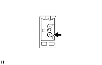
(a) Disconnect the G41 navigation receiver assembly connector.
|
(b) Measure the voltage according to the value(s) in the table below. Standard Voltage:
|
|
| NG | |
REPLACE NAVIGATION RECEIVER ASSEMBLY |
|
|
6. |
REPLACE AMPLIFIER ANTENNA ASSEMBLY |
(a) Replace the amplifier antenna assembly and check if radio broadcasts can
be received normally (See page .gif) ).
).
OK:
Radio broadcasts can be received normally.
| OK | |
NORMAL OPERATION |
|
|
7. |
REPLACE NO. 2 ANTENNA CORD SUB-ASSEMBLY |
(a) Replace the No. 2 antenna cord sub-assembly and check if radio broadcasts
can be received normally (See page ).
OK:
Radio broadcasts can be received normally.
| OK | |
NORMAL OPERATION |
|
|
8. |
REPLACE NO. 2 INSTRUMENT PANEL WIRE |
(a) Replace the No. 2 instrument panel wire and check if radio broadcasts can
be received normally (See page ).
OK:
Radio broadcasts can be received normally.
| OK | |
NORMAL OPERATION |
| NG | |
REPLACE NAVIGATION RECEIVER ASSEMBLY |
 CD Sound Skips
CAUTION / NOTICE / HINT
NOTICE:
After replacing the navigation receiver assembly of vehicles subscribed to pay-type
satellite radio broadcasts, XM radio ID registration is necessary.
PROCEDURE
...
 Illumination for Panel Switch does not Come on with Tail Switch ON
CAUTION / NOTICE / HINT
NOTICE:
After replacing the navigation receiver assembly of vehicles subscribed to pay-type
satellite radio broadcasts, registration of the XM radio ID is necessary.
PROCE ...
Other materials about Toyota 4Runner:
Diagnosis System
DIAGNOSIS SYSTEM
1. DESCRIPTION
(a) Air conditioning system data and Diagnostic Trouble Codes (DTCs) can be read
through the Data Link Connector 3 (DLC3) of the vehicle. When the system seems to
be malfunctioning, use the Techstream to check for malfunct ...
Components
COMPONENTS
ILLUSTRATION
ILLUSTRATION
ILLUSTRATION
ILLUSTRATION
ILLUSTRATION
...
0.0074