Toyota 4Runner: Rear Airbag Sensor Assembly RH Initialization Incomplete (B1633/81,B1638/82)
DESCRIPTION
The circuit for the side collision sensor LH or RH (to determine deployment of the front seat side airbag LH or RH and curtain shield airbag LH or RH) is composed of the center airbag sensor, side airbag sensor LH or RH and rear airbag sensor LH or RH.
The rear airbag sensor LH or RH detect impacts to the vehicle and send signals to the center airbag sensor to determine if the airbag should be deployed.
DTC B1633 or B1638 is stored when a malfunction is detected in the circuit for the rear collision sensor LH or RH (to determine deployment of the curtain shield airbag LH or RH).
|
DTC Code |
DTC Detection Condition |
Trouble Area |
|---|---|---|
|
B1633/81 |
One of the following conditions is met:
|
|
|
B1638/82 |
One of the following conditions is met:
|
|
WIRING DIAGRAM
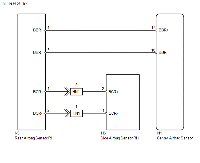
.png)
CAUTION / NOTICE / HINT
NOTICE:
When disconnecting the cable from the negative (-) battery terminal while performing
repairs, some systems need to be initialized after the cable is reconnected (See
page .gif) ).
).
PROCEDURE
|
1. |
CHECK FOR DTC |
(a) Turn the ignition switch off.
HINT:
If a communication error occurs, DTCs for both the LH and RH sides will be stored simultaneously. The malfunctioning area can be identified by turning the ignition switch off and then to ON again.
(b) Turn the ignition switch to ON, and wait for at least 60 seconds.
(c) Check for DTCs (See page ).
Result
|
Result |
Proceed to |
|---|---|
|
DTC B1633 and B1638 are not output |
A |
|
DTC B1638 is output |
B |
|
DTC B1633 is output |
C |
HINT:
Codes other than DTC B1633 and B1638 may be output at this time, but they are not related to this check.
| A | .gif) |
USE SIMULATION METHOD TO CHECK |
| B | |
GO TO STEP 7 |
|
.gif)
|
2. |
CHECK CONNECTION OF CONNECTORS |
(a) Turn the ignition switch off.
(b) Disconnect the cable from the negative (-) battery terminal, and wait for at least 90 seconds.
(c) Check that the connectors are properly connected to the center airbag sensor and rear airbag sensor RH.
OK:
The connectors are properly connected.
| NG | |
CONNECT CONNECTORS PROPERLY |
|
|
3. |
CHECK CONNECTORS |
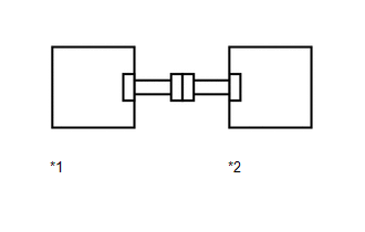
(a) Disconnect the connectors from the center airbag sensor and rear airbag sensor RH.
|
(b) Check that the connectors (on the center airbag sensor side and rear airbag sensor RH side) are not damaged. OK: The connectors are not deformed or damaged. Text in Illustration
|
|
| NG | |
REPLACE FLOOR WIRE |
|
|
4. |
CHECK FLOOR WIRE (CENTER AIRBAG SENSOR - REAR AIRBAG SENSOR RH) |
(a) Connect the cable to the negative (-) battery terminal, and wait for at least 2 seconds.
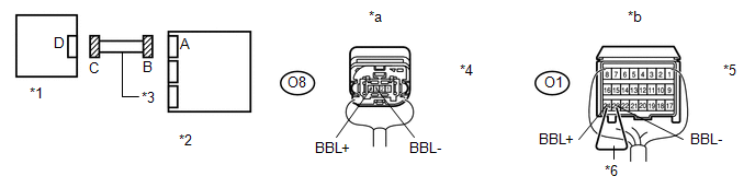
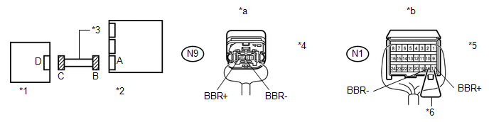 Text in Illustration
|
*1 |
Rear Airbag Sensor RH |
*2 |
Center Airbag Sensor |
|
*3 |
Floor Wire |
*4 |
Connector C |
|
*5 |
Connector B |
*6 |
Service Wire |
|
*a |
Rear view of wire harness connector (to Rear Airbag Sensor RH) |
*b |
Rear view of wire harness connector (to Center Airbag Sensor) |
(b) Measure the voltage according to the value(s) in the table below.
Standard Voltage:
|
Tester Connection |
Switch Condition |
Specified Condition |
|---|---|---|
|
N9-4 (BBR+) - Body ground |
Ignition switch ON |
Below 1 V |
|
N9-3 (BBR-) - Body ground |
Ignition switch ON |
Below 1 V |
(c) Turn the ignition switch off.
(d) Disconnect the cable from the negative (-) battery terminal, and wait for at least 90 seconds.
(e) Using a service wire, connect terminals 17 (BBR+) and 18 (BBR-) of connector B.
NOTICE:
Do not forcibly insert the service wire into the terminals of the connector when connecting a service wire.
(f) Measure the resistance according to the value(s) in the table below.
Standard Resistance:
|
Tester Connection |
Condition |
Specified Condition |
|---|---|---|
|
N9-4 (BBR+) - N9-3 (BBR-) |
Always |
Below 1 Ω |
(g) Disconnect the service wire from connector B.
(h) Measure the resistance according to the value(s) in the table below.
Standard Resistance:
|
Tester Connection |
Condition |
Specified Condition |
|---|---|---|
|
N9-4 (BBR+) - N9-3 (BBR-) |
Always |
1 MΩ or higher |
|
N9-4 (BBR+) - Body ground |
Always |
1 MΩ or higher |
|
N9-3 (BBR-) - Body ground |
Always |
1 MΩ or higher |
| NG | |
REPLACE FLOOR WIRE |
|
|
5. |
CHECK REAR AIRBAG SENSOR RH |
|
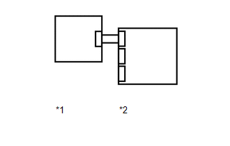
(a) Connect the connector to the center airbag sensor. |
|
(b) Interchange the rear airbag sensor LH with RH and connect the connectors to them.
(c) Connect the cable to the negative (-) battery terminal, and wait for at least 2 seconds.
(d) Turn the ignition switch to ON, and wait for at least 60 seconds.
(e) Clear the DTCs stored in memory (See page
).
(f) Turn the ignition switch off.
(g) Turn the ignition switch to ON, and wait for at least 90 seconds.
(h) Check for DTCs (See page ).
Result
|
Result |
Proceed to |
|---|---|
|
DTC B1633 and B1638 are not output |
A |
|
DTC B1638 is output |
B |
|
DTC B1633 is output |
C |
HINT:
Codes other than DTC B1633 and B1638 may be output at this time, but they are not related to this check.
Text in Illustration|
*1 |
Rear Airbag Sensor LH |
|
*2 |
Center Airbag Sensor |
(i) Turn the ignition switch off.
(j) Disconnect the cable from the negative (-) battery terminal, and wait for at least 90 seconds.
(k) Return the rear airbag sensor LH and RH to their original positions and connect the connectors to them.
| A | |
USE SIMULATION METHOD TO CHECK |
| B | |
REPLACE REAR AIRBAG SENSOR RH |
|
|
6. |
CHECK SIDE AIRBAG SENSOR RH |
|
(a) Interchange the side airbag sensor LH with RH and connect the connectors to them. |
|
(b) Connect the cable to the negative (-) battery terminal, and wait for at least 2 seconds.
(c) Turn the ignition switch to ON, and wait for at least 60 seconds.
(d) Clear the DTCs stored in memory (See page
).
(e) Turn the ignition switch off.
(f) Turn the ignition switch to ON, and wait for at least 90 seconds.
(g) Check for DTCs (See page ).
Result
|
Result |
Proceed to |
|---|---|
|
DTC B1633 and B1638 are not output |
A |
|
DTC B1638 is output |
B |
|
DTC B1633 is output |
C |
HINT:
Codes other than DTC B1633 and B1638 may be output at this time, but they are not related to this check.
Text in Illustration|
*1 |
Side Airbag Sensor LH |
|
*2 |
Rear Airbag Sensor RH |
(h) Turn the ignition switch off.
(i) Disconnect the cable from the negative (-) battery terminal, and wait for at least 90 seconds.
(j) Return the side airbag sensor LH and RH to their original positions and connect the connectors to them.
| C | |
REPLACE CENTER AIRBAG SENSOR ASSEMBLY |
| A | |
USE SIMULATION METHOD TO CHECK |
| B | |
REPLACE SIDE AIRBAG SENSOR ASSEMBLY RH |
|
7. |
CHECK CONNECTION OF CONNECTORS |
(a) Turn the ignition switch off.
(b) Disconnect the cable from the negative (-) battery terminal, and wait for at least 90 seconds.
(c) Check that the connectors are properly connected to the center airbag sensor and rear airbag sensor LH.
OK:
The connectors are properly connected.
| NG | |
CONNECT CONNECTORS PROPERLY |
|
|
8. |
CHECK CONNECTORS |
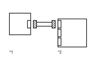
(a) Disconnect the connectors from the center airbag sensor and rear airbag sensor LH.
|
(b) Check that the connectors (on the center airbag sensor side and rear airbag sensor LH side) are not damaged. OK: The connectors are not deformed or damaged. Text in Illustration
|
|
| NG | |
REPLACE NO. 2 FLOOR WIRE |
|
|
9. |
CHECK NO. 2 FLOOR WIRE (CENTER AIRBAG SENSOR - REAR AIRBAG SENSOR LH) |
(a) Connect the cable to the negative (-) battery terminal, and wait for at least 2 seconds.
 Text in Illustration
|
*1 |
Rear Airbag Sensor LH |
*2 |
Center Airbag Sensor |
|
*3 |
No. 2 Floor Wire |
*4 |
Connector C |
|
*5 |
Connector B |
*6 |
Service Wire |
|
*a |
Rear view of wire harness connector (to Rear Airbag Sensor LH) |
*b |
Rear view of wire harness connector (to Center Airbag Sensor) |
(b) Measure the voltage according to the value(s) in the table below.
Standard Voltage:
|
Tester Connection |
Switch Condition |
Specified Condition |
|---|---|---|
|
O8-4 (BBL+) - Body ground |
Ignition switch ON |
Below 1 V |
|
O8-3 (BBL-) - Body ground |
Ignition switch ON |
Below 1 V |
(c) Turn the ignition switch off.
(d) Disconnect the cable from the negative (-) battery terminal, and wait for at least 90 seconds.
(e) Using a service wire, connect terminals 24 (BBL+) and 23 (BBL-) of connector B.
NOTICE:
Do not forcibly insert the service wire into the terminals of the connector when connecting a service wire.
(f) Measure the resistance according to the value(s) in the table below.
Standard Resistance:
|
Tester Connection |
Condition |
Specified Condition |
|---|---|---|
|
O8-4 (BBL+) - O8-3 (BBL-) |
Always |
Below 1 Ω |
(g) Disconnect the service wire from connector B.
(h) Measure the resistance according to the value(s) in the table below.
Standard Resistance:
|
Tester Connection |
Condition |
Specified Condition |
|---|---|---|
|
O8-4 (BBL+) - O8-3 (BBL-) |
Always |
1 MΩ or higher |
|
O8-4 (BBL+) - Body ground |
Always |
1 MΩ or higher |
|
O8-3 (BBL-) - Body ground |
Always |
1 MΩ or higher |
| NG | |
REPLACE NO. 2 FLOOR WIRE |
|
|
10. |
CHECK REAR AIRBAG SENSOR LH |
|
(a) Connect the connector to the center airbag sensor. |
|
(b) Interchange the rear airbag sensor LH with RH and connect the connectors to them.
(c) Connect the cable to the negative (-) battery terminal, and wait for at least 2 seconds.
(d) Turn the ignition switch to ON, and wait for at least 60 seconds.
(e) Clear the DTCs stored in memory (See page
).
(f) Turn the ignition switch off.
(g) Turn the ignition switch to ON, and wait for at least 90 seconds.
(h) Check for DTCs (See page ).
Result
|
Result |
Proceed to |
|---|---|
|
DTC B1633 and B1638 are not output |
A |
|
DTC B1633 is output |
B |
|
DTC B1638 is output |
C |
HINT:
Codes other than DTC B1633 and B1638 may be output at this time, but they are not related to this check.
Text in Illustration|
*1 |
Rear Airbag Sensor RH |
|
*2 |
Center Airbag Sensor |
(i) Turn the ignition switch off.
(j) Disconnect the cable from the negative (-) battery terminal, and wait for at least 90 seconds.
(k) Return the rear airbag sensor RH and LH to their original positions and connect the connectors to them.
| A | |
USE SIMULATION METHOD TO CHECK |
| B | |
REPLACE REAR AIRBAG SENSOR LH |
|
|
11. |
CHECK SIDE AIRBAG SENSOR LH |
|
(a) Interchange the side airbag sensor LH with RH and connect the connectors to them. |
|
(b) Connect the cable to the negative (-) battery terminal, and wait for at least 2 seconds.
(c) Turn the ignition switch to ON, and wait for at least 60 seconds.
(d) Clear the DTCs stored in memory (See page
).
(e) Turn the ignition switch off.
(f) Turn the ignition switch to ON, and wait for at least 90 seconds.
(g) Check for DTCs (See page ).
Result
|
Result |
Proceed to |
|---|---|
|
DTC B1633 and B1638 are not output |
A |
|
DTC B1633 is output |
B |
|
DTC B1638 is output |
C |
HINT:
Codes other than DTC B1633 and B1638 may be output at this time, but they are not related to this check.
Text in Illustration|
*1 |
Side Airbag Sensor RH |
|
*2 |
Rear Airbag Sensor LH |
(h) Turn the ignition switch off.
(i) Disconnect the cable from the negative (-) battery terminal, and wait for at least 90 seconds.
(j) Return the side airbag sensor RH and LH to their original positions and connect the connectors to them.
| C | |
REPLACE CENTER AIRBAG SENSOR ASSEMBLY |
| A | |
USE SIMULATION METHOD TO CHECK |
| B | |
REPLACE SIDE AIRBAG SENSOR ASSEMBLY LH |
 Rear Airbag Sensor RH Circuit Malfunction (B1630/23,B1635/24)
DESCRIPTION
The rear airbag sensor consists of the safing sensor, diagnostic circuit,
lateral deceleration sensor, etc.
If the center airbag sensor receives signals from the lateral de ...
 Lost Communication with Front Satellite Sensor Bus (B161A/8A)
DESCRIPTION
The front collision sensor circuit (front airbag sensor RH circuit and front
airbag sensor LH circuit) is composed of the center airbag sensor assembly, front
airbag sensor RH and fro ...
Other materials about Toyota 4Runner:
Disassembly
DISASSEMBLY
CAUTION / NOTICE / HINT
HINT:
Use the same procedure for the RH and LH sides.
The procedure listed below is for the LH side.
PROCEDURE
1. REMOVE FRONT FENDER OUTSIDE MOULDING PAD LH
(a) Remove the front fender outside moul ...
Freeze Frame Data
FREEZE FRAME DATA
1. CHECK FREEZE FRAME DATA
(a) Connect the Techstream to the DLC3.
(b) Turn the ignition switch to ON.
(c) Turn the Techstream on.
(d) Enter the following menus: Body Electrical / Navigation System / Trouble
Codes.
(e) Select a DTC to ...
0.0066