Toyota 4Runner: Rear Differential Lock Control Switch
Components
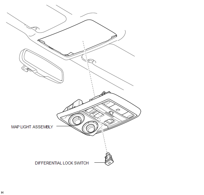
COMPONENTS
ILLUSTRATION
Inspection
INSPECTION
PROCEDURE
1. INSPECT DIFFERENTIAL LOCK SWITCH
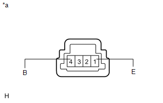
(a) Measure the resistance according to the value(s) in the table below.
Standard Resistance:
|
Tester Connection |
Switch Condition |
Specified Condition |
|---|---|---|
|
1 (E) - 4 (B) |
Pressed |
Below 1 Ω |
|
Not pressed |
100 kΩ or higher |
|
*a |
Component without harness connected (Differential Lock Switch) |
If the result is not as specified, replace the differential lock switch.
Removal
REMOVAL
PROCEDURE
1. REMOVE MAP LIGHT ASSEMBLY
.gif)
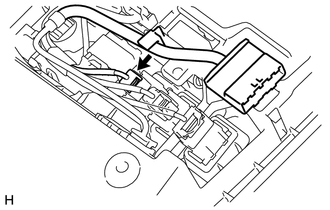
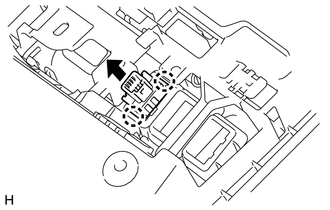
2. REMOVE DIFFERENTIAL LOCK SWITCH
|
(a) Disconnect the differential lock switch connector. |
|
|
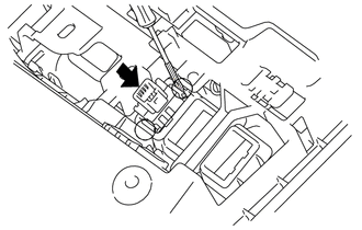
(b) Using a screwdriver, detach the 2 claws and remove the differential lock switch from the map light assembly. HINT: Tape the screwdriver tip before use. |
|
Installation
INSTALLATION
PROCEDURE
1. INSTALL DIFFERENTIAL LOCK SWITCH
|
(a) Attach the 2 claws to install the differential lock switch to the map light assembly. |
|
(b) Connect the connector.
2. INSTALL MAP LIGHT ASSEMBLY
.gif)
 Replacement
REPLACEMENT
PROCEDURE
1. REMOVE REAR PROPELLER SHAFT ASSEMBLY
(a) for 2WD:
Remove the rear propeller shaft assembly (See page
).
(b) for 4WD:
Remove the rear propeller shaft assembly (See page ...
 Rear Differential Lock Position Switch
Components
COMPONENTS
ILLUSTRATION
Inspection
INSPECTION
PROCEDURE
1. INSPECT REAR DIFFERENTIAL LOCK POSITION SWITCH
(a) Measure the resistance according to the value(s) in the ...
Other materials about Toyota 4Runner:
Precaution
PRECAUTION
1. BASIC REPAIR HINT
(a) HINTS ON OPERATIONS
1
Attire
Always wear a clean uniform.
Hat and safety shoes must be worn.
2
Vehicle protection ...
Parking Brake Switch Circuit
DESCRIPTION
This circuit is from the parking brake switch assembly to the radio and display
receiver assembly.
WIRING DIAGRAM
PROCEDURE
1.
CHECK BRAKE WARNING LIGHT
(a) Check that the brake warning light comes on when t ...
0.0072