Toyota 4Runner: Rear Door Courtesy Switch
Components
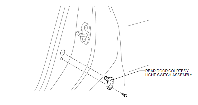
COMPONENTS
ILLUSTRATION
Inspection
INSPECTION
PROCEDURE
1. INSPECT REAR DOOR COURTESY LIGHT SWITCH ASSEMBLY
|
(a) Measure the resistance according to the value(s) in the table below. Standard Resistance:
If the result is not as specified, replace the rear door courtesy light switch assembly. Text in Illustration
|
|
.png)
Removal
REMOVAL
CAUTION / NOTICE / HINT
HINT:
- Use the same procedure for the RH and LH sides.
- The procedure listed below is for the LH side.
PROCEDURE
1. REMOVE REAR DOOR COURTESY LIGHT SWITCH ASSEMBLY
|
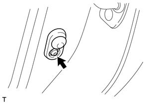
(a) Using a T30 "TORX" socket wrench, remove the screw and courtesy light switch. |
|
(b) Disconnect the connector.
Installation
INSTALLATION
CAUTION / NOTICE / HINT
HINT:
- Use the same procedure for the RH and LH sides.
- The procedure listed below is for the LH side.
PROCEDURE
1. INSTALL REAR DOOR COURTESY LIGHT SWITCH ASSEMBLY
(a) Connect the connector.
(b) Using a T30 "TORX" socket wrench, install the courtesy light switch with the screw.
 Personal Light(for Rear Door)
Components
COMPONENTS
ILLUSTRATION
Removal
REMOVAL
CAUTION / NOTICE / HINT
HINT:
Use the same procedure for the RH and LH sides.
The procedure listed below is for the LH side. ...
 Relay
Relay
On-vehicle Inspection
ON-VEHICLE INSPECTION
PROCEDURE
1. INSPECT DOME RELAY
(a) Measure the resistance according to the value(s) in the table below.
Standard Resistance:
...
Other materials about Toyota 4Runner:
Disassembly
DISASSEMBLY
PROCEDURE
1. REMOVE FRONT NO. 2 AXLE INBOARD JOINT BOOT CLAMP
(a) Hold the drive shaft lightly in a vise between aluminum plates.
(b) Using pliers, remove the front No. 2 axle inboard joint boot clamp
as shown in the illustration ...
LVDS Signal Malfunction (from Extension Module) (B1532)
DESCRIPTION
DTC No.
DTC Detection Condition
Trouble Area
B1532
When one of the conditions below is met:
Stereo component tuner assembly is/was not connected while the
ignition sw ...
0.0067