Toyota 4Runner: Personal Light(for Rear Door)
Components
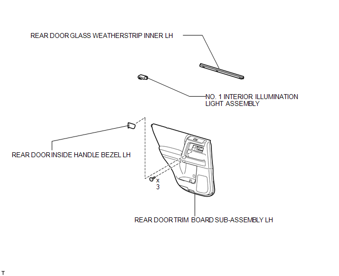
COMPONENTS
ILLUSTRATION
Removal
REMOVAL
CAUTION / NOTICE / HINT
HINT:
- Use the same procedure for the RH and LH sides.
- The procedure listed below is for the LH side.
PROCEDURE
1. REMOVE REAR DOOR INSIDE HANDLE BEZEL LH
.gif)
2. REMOVE REAR DOOR TRIM BOARD SUB-ASSEMBLY LH
3. REMOVE REAR DOOR GLASS WEATHERSTRIP INNER LH
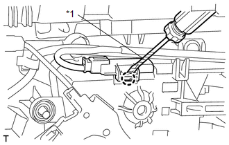
4. REMOVE NO. 1 INTERIOR ILLUMINATION LIGHT ASSEMBLY
|
(a) Using a screwdriver, detach the claw and remove the light. HINT: Tape the screwdriver tip before use. Text in Illustration
|
|
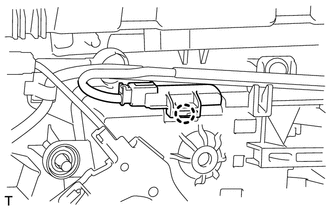
(b) Disconnect the connector.
Inspection
INSPECTION
PROCEDURE
1. INSPECT NO. 1 INTERIOR ILLUMINATION LIGHT ASSEMBLY
|
(a) Apply battery voltage to the connector and check the LED illumination. OK:
If the result is not as specified, replace the No. 1 interior illumination light assembly. Text in Illustration
|
|
.png)
Installation
INSTALLATION
CAUTION / NOTICE / HINT
HINT:
- Use the same procedure for the RH and LH sides.
- The procedure listed below is for the LH side.
PROCEDURE
1. INSTALL NO. 1 INTERIOR ILLUMINATION LIGHT ASSEMBLY
|
(a) Connect the connector. |
|
(b) Attach the claw to install the light.
2. INSTALL REAR DOOR GLASS WEATHERSTRIP INNER LH
.gif)
3. INSTALL REAR DOOR TRIM BOARD SUB-ASSEMBLY LH
4. INSTALL REAR DOOR INSIDE HANDLE BEZEL LH
 Personal Light(for Front Door)
Components
COMPONENTS
ILLUSTRATION
Inspection
INSPECTION
PROCEDURE
1. INSPECT NO. 1 INTERIOR ILLUMINATION LIGHT ASSEMBLY
(a) Apply battery voltage to the connector and check th ...
 Rear Door Courtesy Switch
Components
COMPONENTS
ILLUSTRATION
Inspection
INSPECTION
PROCEDURE
1. INSPECT REAR DOOR COURTESY LIGHT SWITCH ASSEMBLY
(a) Measure the resistance according to the value(s) in t ...
Other materials about Toyota 4Runner:
Removal
REMOVAL
PROCEDURE
1. REMOVE REAR NO. 1 SPOILER COVER
(a) Detach the 4 clips and remove the rear No. 1 spoiler cover.
2. REMOVE REAR SPOILER SUB-ASSEMBLY
(a) Remove the 4 grommets and 4 bolts.
...
Telephone Microphone
Components
COMPONENTS
ILLUSTRATION
ILLUSTRATION
Removal
REMOVAL
PROCEDURE
1. REMOVE DRIVE MONITOR SWITCH
2. REMOVE MAP LIGHT ASSEMBLY
3. REMOVE TELEPHONE MICROPHONE ASSEMBLY
(a) Disconnect the 6 connectors.
...
0.0249