Toyota 4Runner: Rear Washer does not Operate
DESCRIPTION
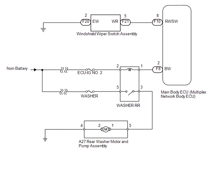
The windshield wiper switch controls the rear washer motor and pump.
WIRING DIAGRAM
CAUTION / NOTICE / HINT
NOTICE:
Inspect the fuses for circuits related to this system before performing the following inspection procedure.
PROCEDURE
|
1. |
READ VALUE USING TECHSTREAM (WINDSHIELD WIPER SWITCH) |
(a) Use the Data List to check if the rear washer is functioning properly (See
page .gif) ).
).
Main Body
|
Tester Display |
Measurement Item/Range |
Normal Condition |
Diagnostic Note |
|---|---|---|---|
|
Rear Washer SW Signal |
Rear washer switch / ON or OFF |
ON: Rear washer switch on OFF: Rear washer switch off |
- |
OK:
On the Techstream screen, each item changes between ON and OFF according to the above chart.
| NG | .gif) |
GO TO STEP 9 |
|
.gif)
|
2. |
PERFORM ACTIVE TEST USING TECHSTREAM (WASHER RR RELAY) |
(a) Using the Techstream, perform the Active Test (See page
).
Main Body
|
Tester Display |
Test Part |
Control Range |
Diagnostic Note |
|---|---|---|---|
|
Rear Wiper Washer Motor Relay |
WASHER RR relay operation |
ON/OFF |
- |
OK:
The rear washer motor operates normally.
| OK | |
REPLACE MAIN BODY ECU (MULTIPLEX NETWORK BODY ECU) |
|
|
3. |
INSPECT WASHER RR RELAY |
|
(a) Remove the WASHER RR relay from the engine room relay block, junction block. |
|
.png)
(b) Measure the resistance according to the value(s) in the table below.
Standard Resistance:
|
Tester Connection |
Condition |
Specified Condition |
|---|---|---|
|
3 - 5 |
Battery voltage is not applied to terminals 1 and 2 |
10 kΩ or higher |
|
Battery voltage is applied to terminals 1 and 2 |
Below 1 Ω |
| NG | |
REPLACE WASHER RR RELAY |
|
|
4. |
CHECK HARNESS AND CONNECTOR (BATTERY - WASHER RR RELAY) |
|
(a) Remove the WASHER RR relay from the engine room relay block, junction block. |
|
.png)
(b) Measure the voltage according to the value(s) in the table below.
Standard Voltage:
|
Tester Connection |
Switch Condition |
Specified Condition |
|---|---|---|
|
RR WASHER relay terminal 2 - Body ground |
Ignition switch ON |
11 to 14 V |
|
RR WASHER relay terminal 2 - Body ground |
Ignition switch off |
Below 1 V |
|
RR WASHER relay terminal 5 - Body ground |
Ignition switch ON |
11 to 14 V |
|
RR WASHER relay terminal 5 - Body ground |
Ignition switch off |
Below 1 V |
|
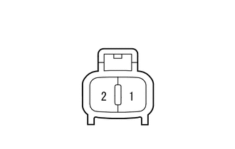
*a |
Front view of wire harness connector (to WASHER RR Relay) |
| NG | |
REPAIR OR REPLACE HARNESS OR CONNECTOR |
|
|
5. |
CHECK HARNESS AND CONNECTOR (WASHER RR RELAY - MAIN BODY ECU) |
(a) Remove the WASHER RR relay from the engine room relay block, junction block.
(b) Disconnect the F8 main body ECU connector.
(c) Measure the resistance according to the value(s) in the table below.
Standard Resistance:
|
Tester Connection |
Condition |
Specified Condition |
|---|---|---|
|
F8-2 (BW) - WASHER RR relay terminal 1 |
Always |
Below 1 Ω |
|
F8-2 (BW) - Body ground |
Always |
10 kΩ or higher |
| NG | |
REPAIR OR REPLACE HARNESS OR CONNECTOR |
|
|
6. |
INSPECT REAR WASHER MOTOR AND PUMP ASSEMBLY |
|
(a) Remove the rear washer motor and pump (See page
|
|
(b) Apply battery voltage to the rear wiper motor and check the operation of the rear wiper motor.
OK:
|
Measurement Condition |
Specified Condition |
|---|---|
|
Battery positive (+) → 1 Battery negative (-) → 2 |
Rear washer motor operation is normal |
| NG | |
REPLACE REAR WASHER MOTOR AND PUMP ASSEMBLY |
|
|
7. |
CHECK WIRE HARNESS (REAR WASHER MOTOR AND PUMP ASSEMBLY) |
(a) Disconnect the A27 level warning switch connector.
(b) Measure the resistance according to the value(s) in the table below.
Standard Resistance:
|
Tester Connection |
Condition |
Specified Condition |
|---|---|---|
|
A27-5 - 1 |
Always |
Below 1 Ω |
|
A27-4 - 2 |
Always |
Below 1 Ω |
|
A27-5 - Body ground |
Always |
10 kΩ or higher |
|
A27-4 - Body ground |
Always |
10 kΩ or higher |
| NG | |
REPAIR OR REPLACE HARNESS OR CONNECTOR |
|
|
8. |
CHECK HARNESS AND CONNECTOR (REAR WASHER MOTOR AND PUMP ASSEMBLY - WASHER RR RELAY AND BODY GROUND) |
(a) Disconnect the A27 rear washer motor connector.
(b) Remove the WASHER RR relay from the engine room relay block, junction block.
(c) Measure the resistance according to the value(s) in the table below.
Standard Resistance:
|
Tester Connection |
Condition |
Specified Condition |
|---|---|---|
|
A27-5 - WASHER RR relay terminal 3 |
Always |
Below 1 Ω |
|
A27-4 - Body ground |
Always |
Below 1 Ω |
|
A27-5 - Body ground |
Always |
10 kΩ or higher |
| OK | |
REPLACE MAIN BODY ECU (MULTIPLEX NETWORK BODY ECU) |
| NG | |
REPAIR OR REPLACE HARNESS OR CONNECTOR |
|
9. |
INSPECT WINDSHIELD WIPER SWITCH ASSEMBLY |
|
(a) Remove the windshield wiper switch (See page
|
|
(b) Measure the resistance according to the value(s) in the table below.
Standard Resistance:
|
Tester Connection |
Switch Condition |
Specified Condition |
|---|---|---|
|
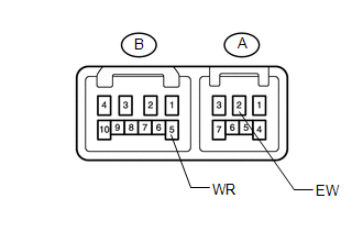
B-5 (WR) - A-2 (EW) |
Rear washer switch on |
Below 1 Ω |
|
B-5 (WR) - A-2 (EW) |
Rear washer switch off |
10 kΩ or higher |
| NG | |
REPLACE WINDSHIELD WIPER SWITCH ASSEMBLY |
|
|
10. |
CHECK HARNESS AND CONNECTOR (WINDSHIELD WIPER SWITCH ASSEMBLY - MAIN BODY ECU AND BODY GROUND) |
(a) Disconnect the F20 and F21 windshield wiper switch connectors.
(b) Disconnect the F10 main body ECU connector.
(c) Measure the resistance according to the value(s) in the table below.
Standard Resistance:
|
Tester Connection |
Condition |
Specified Condition |
|---|---|---|
|
F21-5 (WR) - F10-8 (RWSW) |
Always |
Below 1 Ω |
|
F20-2 (EW) - Body ground |
Always |
Below 1 Ω |
|
F21-5 (WR) - Body ground |
Always |
10 kΩ or higher |
| OK | |
REPLACE MAIN BODY ECU (MULTIPLEX NETWORK BODY ECU) |
| NG | |
REPAIR OR REPLACE HARNESS OR CONNECTOR |
 Rear Wiper does not Operate
DESCRIPTION
The windshield wiper switch controls the rear wiper motor.
WIRING DIAGRAM
CAUTION / NOTICE / HINT
HINT:
Since the wiper and washer system has functions that use LIN communication, f ...
 Washer Fluid Level Warning Switch Circuit
DESCRIPTION
When the volume of washer fluid decreases to below a certain level (when the
level warning switch is turned on), the multi-information display in the combination
meter assembly displa ...
Other materials about Toyota 4Runner:
Loading CDs
Loading a CD (type A and B)
Insert a CD.
Loading a CD (type C)
Press
.
When the indicator on the slot turns
from amber to green, insert a CD.
Loading multiple CDs (type C only)
Press and hold
until you hear a beep.
When the indicator on th ...
Installation
INSTALLATION
PROCEDURE
1. INSTALL LOWER NO. 1 INSTRUMENT PANEL AIRBAG ASSEMBLY
(a) Connect the connector.
NOTICE:
When handling the airbag connector, take care not to damage the airbag
wire harness.
...
0.0105