Toyota 4Runner: Washer Fluid Level Warning Switch Circuit
DESCRIPTION
When the volume of washer fluid decreases to below a certain level (when the level warning switch is turned on), the multi-information display in the combination meter assembly displays "LOW WASHER FLUID" to warn the driver.
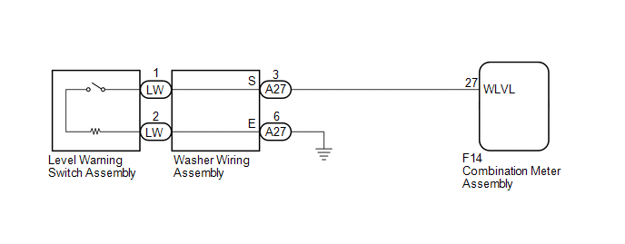
WIRING DIAGRAM
PROCEDURE
|
1. |
READ VALUE USING TECHSTREAM (WASHER SWITCH) |
(a) Use the Data List to check if the level warning switch assembly is functioning
properly (See page .gif) ).
).
Combination Meter
|
Tester Display |
Measurement Item/Range |
Normal Condition |
Diagnostic Note |
|---|---|---|---|
|
Washer Switch |
Level warning switch / ON or OFF |
ON: Washer jar and tank empty OFF: Washer jar and tank full |
- |
OK:
On the Techstream screen, each item changes between ON and OFF according to the above chart.
| OK | .gif) |
PROCEED TO NEXT SUSPECTED AREA SHOWN IN PROBLEM SYMPTOMS TABLE |
|
.gif)
|
2. |
INSPECT LEVEL WARNING SWITCH ASSEMBLY |
(a) Inspect the level warning switch assembly (See page
).
| NG | |
REPLACE WASHER FLUID LEVEL WARNING SWITCH ASSEMBLY |
|
|
3. |
CHECK WASHER WIRING ASSEMBLY |
(a) Disconnect the A27 and LW washer wiring assembly connectors.
(b) Measure the resistance according to the value(s) in the table below.
Standard Resistance:
|
Tester Connection |
Condition |
Specified Condition |
|---|---|---|
|
A27-3 (S) - LW-1 |
Always |
Below 1 Ω |
|
A27-6 (E) - LW-2 |
Always |
Below 1 Ω |
|
A27-3 (S) or LW-1 - Body ground |
Always |
10 kΩ or higher |
|
A27-6 (E) or LW-2 - Body ground |
Always |
10 kΩ or higher |
| NG | |
REPLACE WASHER WIRING ASSEMBLY |
|
|
4. |
CHECK HARNESS AND CONNECTOR (LEVEL WARNING SWITCH ASSEMBLY - COMBINATION METER ASSEMBLY AND BODY GROUND) |
(a) Disconnect the A27 washer wiring assembly connector.
(b) Disconnect the F14 combination meter assembly connector.
(c) Measure the resistance according to the value(s) in the table below.
Standard Resistance:
|
Tester Connection |
Condition |
Specified Condition |
|---|---|---|
|
A27-3 (S) - F14-27 (WLVL) |
Always |
Below 1 Ω |
|
A27-6 (E) - Body ground |
Always |
Below 1 Ω |
|
A27-3 (S) or F14-27 (WLVL) - Body ground |
Always |
10 kΩ or higher |
| OK | |
PROCEED TO NEXT SUSPECTED AREA SHOWN IN PROBLEM SYMPTOMS TABLE |
| NG | |
REPAIR OR REPLACE HARNESS OR CONNECTOR |
 Rear Washer does not Operate
DESCRIPTION
The windshield wiper switch controls the rear washer motor and pump.
WIRING DIAGRAM
CAUTION / NOTICE / HINT
NOTICE:
Inspect the fuses for circuits related to this system before perf ...
 Wiper Switch
...
Other materials about Toyota 4Runner:
Engine Immobiliser System Malfunction (B2799)
DESCRIPTION
This DTC is stored when one of the following occurs: 1) the ECM detects errors
in its own communications with the transponder key ECU assembly; 2) the ECM detects
errors in the communication lines; or 3) the ECU - ECM communication ID between ...
Transmitter Battery(w/o Smart Key System)
Replacement
REPLACEMENT
CAUTION / NOTICE / HINT
NOTICE:
Take extra care when handling these precision electronic components.
PROCEDURE
1. REMOVE TRANSMITTER HOUSING COVER
(a) Twist a screwdriver in the direction of the arrow in the illustra ...
0.0086