Toyota 4Runner: Reassembly
REASSEMBLY
PROCEDURE
1. INSTALL KEY INTERLOCK SOLENOID WIRE (w/o Smart Key System)
(a) Install the key interlock solenoid wire on to the install the ignition switch.
2. INSTALL IGNITION SWITCH ASSEMBLY (w/o Smart Key System)
|
(a) Install the ignition switch onto the steering column upper bracket with the 2 screws. |
|
.png)
3. INSTALL KEY INTERLOCK SOLENOID (w/o Smart Key System)
|
(a) Install the key interlock solenoid onto the steering column upper bracket with the 2 screws. |
|
.png)
(b) Connect the connector.
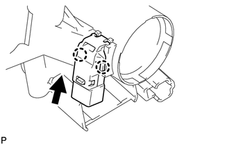
4. INSTALL UNLOCK WARNING SWITCH ASSEMBLY (w/o Smart Key System)
|
(a) Attach the 2 claws to install the unlock warning switch onto the steering column upper bracket. HINT: Slide the unlock warning switch in the direction shown by the arrow in the illustration to install it. |
|
5. INSTALL IGNITION SWITCH LOCK CYLINDER ASSEMBLY (w/o Smart Key System)
(a) Turn the ignition switch to ON (ACC).
|
(b) Install the ignition switch lock cylinder into the steering column upper bracket. |
|
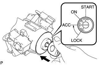
(c) Make sure that the ignition switch lock cylinder is securely fixed onto the ignition switch lock cylinder.
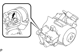
6. INSPECT STEERING LOCK OPERATION (w/o Smart Key System)
|
(a) Remove the key and check that the steering lock function is activated. |
|
|
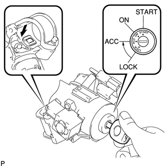
(b) Insert the key, turn the ignition switch ON (ACC) and check that the steering lock function is deactivated. |
|
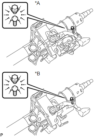
7. INSTALL STEERING LOCK ACTUATOR ASSEMBLY
HINT:
When replacing the steering lock actuator assembly (w/ smart key system), perform
key registration (See page .gif) ).
).
(a) Temporarily install the steering lock actuator assembly with a new tapered-head bolt.
|
(b) Tighten the tapered-head bolt until the bolt head breaks off. Text in Illustration
|
|
 Disassembly
DISASSEMBLY
PROCEDURE
1. REMOVE STEERING LOCK ACTUATOR ASSEMBLY
(a) Using a center punch, mark the center of the tapered-head bolt.
(b) Using a 3 to 4 mm (0.118 to 0.157 in.) drill, drill a hole i ...
 Installation
INSTALLATION
PROCEDURE
1. CONNECT NO. 2 STEERING INTERMEDIATE SHAFT SUB-ASSEMBLY
(a) Align the matchmarks on the No. 2 steering intermediate shaft and power steering
gear.
(b) Install the bolt.
...
Other materials about Toyota 4Runner:
Terminals Of Ecm
TERMINALS OF ECM
1. CHECK ECM
HINT:
The standard voltage at each ECM terminal is shown in the table below.
In the table, first follow the information under "Condition". Look under "Terminal
No. (Symbol)" for the terminals to inspect ...
Reassembly
REASSEMBLY
PROCEDURE
1. INSTALL DIFFERENTIAL CASE ASSEMBLY
(a) Install the rear differential side gear thrust washer to the rear differential
side gear.
(b) Install the rear differential pinion thrust washer and rear differential
pinion to the rear d ...
0.0176