Toyota 4Runner: Reassembly
REASSEMBLY
PROCEDURE
1. INSTALL FRONT UPPER BALL JOINT DUST COVER LH
|
(a) Pack the upper arm ball joint with MP grease. Grease capacity: 8.0 g (0.282 oz.) Text in Illustration
|
|
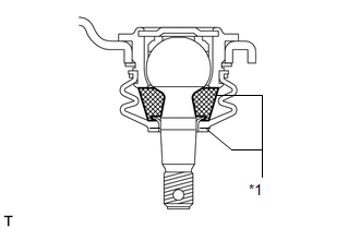
(b) Apply MP grease to the locations shown in the illustration.
NOTICE:
Do not apply MP grease to the tapered or threaded parts of the ball joint.
(c) Install the dust cover to the upper arm.
|
(d) Using a snap ring expander, install the dust cover set ring. NOTICE: Make sure the set ring is securely installed in the groove. |
|
.png)
2. INSTALL FRONT SUSPENSION UPPER ARM BUSH LH
|
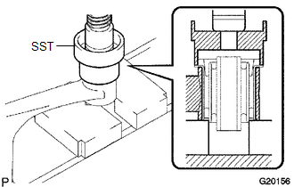
(a) Using SST and a press, press in a new bush. SST: 09710-26011 09710-05061 HINT: Press in the rear side bush using the same procedure as for the front side. |
|
 Inspection
INSPECTION
PROCEDURE
1. INSPECT FRONT SUSPENSION UPPER ARM ASSEMBLY LH
(a) As shown in the illustration, flip the ball joint stud back and forth
5 times before installing the nut.
...
 Installation
INSTALLATION
CAUTION / NOTICE / HINT
HINT:
Use the same procedure for the RH and LH sides.
The procedure listed below is for the LH side.
A bolt without a torque specification is sh ...
Other materials about Toyota 4Runner:
How To Proceed With Troubleshooting
CAUTION / NOTICE / HINT
HINT:
*: Use the Techstream.
PROCEDURE
1.
VEHICLE BROUGHT TO WORKSHOP
NEXT
2.
CUSTOMER PROBLEM ANALYSIS
...
Open or Short in Rear Speed Sensor RH Circuit (C1407,C1408)
DESCRIPTION
Refer to DTCs C1401 and C1402 (See page ).
DTC Code
DTC Detection Condition
Trouble Area
C1407
C1408
Either condition is met:
An open in the speed sensor signal circui ...
0.0271