Toyota 4Runner: Reassembly
REASSEMBLY
PROCEDURE
1. INSTALL NO. 1 ULTRASONIC SENSOR RETAINER
.gif)
2. INSTALL NO. 2 ULTRASONIC SENSOR RETAINER
3. INSTALL ULTRASONIC SENSOR CLIP
4. INSTALL NO. 1 ULTRASONIC SENSOR
5. INSTALL REAR BUMPER CENTER MOULDING
(a) Attach the 4 claws to install the rear bumper center moulding.
(b) Install the 6 outside moulding retainers.
6. INSTALL NO. 1 REAR BUMPER PLATE
(a) Attach the claw to install the No. 1 rear bumper plate.
(b) Install the outside moulding retainer.
7. INSTALL REAR BUMPER PLATE RH
(a) Attach the claw to install the rear bumper plate RH.
(b) Install the outside moulding retainer.
8. INSTALL REAR BUMPER PLATE LH
(a) Attach the claw to install the rear bumper plate LH.
(b) Install the 2 outside moulding retainers.
9. INSTALL REAR BUMPER SIDE BRACKET LH
(a) Install the rear bumper side bracket LH with the 2 screws and clip.
10. INSTALL REAR BUMPER SIDE BRACKET RH
HINT:
Use the same procedure as for the LH side.
11. INSTALL NO. 3 FLOOR WIRE
(a) Clean the rear bumper surface.
(1) Using a heat light, heat the rear bumper surface.
(2) Remove the double-sided tape from the rear bumper surface.
(3) Wipe off any tape adhesive residue with cleaner.
(b) Attach the 4 clamps to connect the 4 connectors.
(c) Install the No. 3 floor wire with the new 3 pieces of tape as shown in the illustration.
HINT:
- With the wire harness contacting the rear bumper cover, wrap tape around as much of the wire harness as possible.
- Do not reuse the tape.
- Be sure to install the wire harness so that it is centered between the guidelines labeled B and attach the tape so that its edges are aligned with the guidelines labeled A.
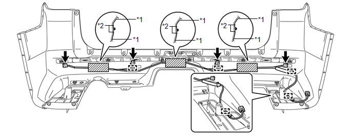 Text in Illustration
|
*1 |
Guideline A |
*2 |
Guideline B |
 Disassembly
DISASSEMBLY
PROCEDURE
1. REMOVE NO. 3 FLOOR WIRE
(a) Disconnect the 4 connectors and remove the 3 pieces of tape.
(b) Detach the 4 clamps to remove the No. 3 floor wire.
2. REMOVE REAR BUMPER S ...
 Installation
INSTALLATION
CAUTION / NOTICE / HINT
HINT:
A bolt without a torque specification is shown in the standard bolt chart (See
page ).
PROCEDURE
1. INSTALL PINTLE HOOK SUPPORT TUBE SUB-ASSEMBLY (w/ ...
Other materials about Toyota 4Runner:
On-vehicle Inspection
ON-VEHICLE INSPECTION
PROCEDURE
1. CHECK SHIFT LOCK OPERATION
(a) Move the shift lever to P.
(b) Turn the ignition switch off.
(c) Check that the shift lever cannot be moved from P.
(d) Turn the ignition switch to on (IG), depress the brake pedal and che ...
Terminals Of Ecu
TERMINALS OF ECU
1. CHECK TIRE PRESSURE WARNING ECU
HINT:
Inspect the connector from the back side.
(a) Disconnect the F7 ECU connector.
(b) Measure the voltage according to the value(s) in the table below.
Terminal No. (Symbol)
W ...
0.0066