Toyota 4Runner: Disassembly
DISASSEMBLY
PROCEDURE
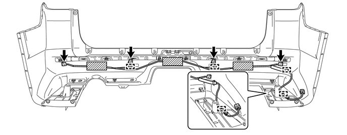
1. REMOVE NO. 3 FLOOR WIRE
(a) Disconnect the 4 connectors and remove the 3 pieces of tape.
(b) Detach the 4 clamps to remove the No. 3 floor wire.
2. REMOVE REAR BUMPER SIDE BRACKET LH
|
(a) Remove the clip and 2 screws. |
|
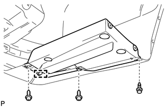
(b) Detach the guide to remove the rear bumper side bracket LH.
3. REMOVE REAR BUMPER SIDE BRACKET RH
HINT:
Use the same procedure as for the LH side.
4. REMOVE REAR BUMPER PLATE LH
|
(a) Remove the 2 outside moulding retainers. |
|
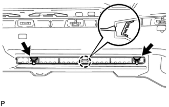
(b) Detach the claw to remove the rear bumper plate LH.
5. REMOVE REAR BUMPER PLATE RH
|
(a) Remove the outside moulding retainer. |
|
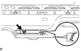
(b) Detach the claw to remove the rear bumper plate RH.
6. REMOVE NO. 1 REAR BUMPER PLATE
|
(a) Remove the outside moulding retainer. |
|
(b) Detach the claw to remove the No. 1 rear bumper plate.
7. REMOVE REAR BUMPER CENTER MOULDING
(a) Remove the 6 outside moulding retainers.
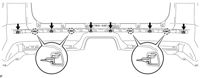
(b) Detach the 4 claws to remove the rear bumper center moulding.
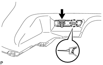
8. REMOVE NO. 1 ULTRASONIC SENSOR
.gif)
9. REMOVE ULTRASONIC SENSOR CLIP
10. REMOVE NO. 2 ULTRASONIC SENSOR RETAINER
11. REMOVE NO. 1 ULTRASONIC SENSOR RETAINER
 Removal
REMOVAL
PROCEDURE
1. REMOVE JACK BOX HOLE COVER
2. REMOVE REAR QUARTER PANEL MUDGUARD LH
3. REMOVE REAR QUARTER PANEL MUDGUARD RH
HINT:
Use the same procedure as for the LH side.
4. REMOV ...
 Reassembly
REASSEMBLY
PROCEDURE
1. INSTALL NO. 1 ULTRASONIC SENSOR RETAINER
2. INSTALL NO. 2 ULTRASONIC SENSOR RETAINER
3. INSTALL ULTRASONIC SENSOR CLIP
4. INSTALL NO. 1 ULTRASONIC SENSOR
5. I ...
Other materials about Toyota 4Runner:
Problem Symptoms Table
PROBLEM SYMPTOMS TABLE
HINT:
Use the table below to help determine the cause of problem symptoms.
If multiple suspected areas are listed, the potential causes of the symptoms
are listed in order of probability in the "Suspected Area" ...
Ignition Hold Monitor Malfunction (B2271)
DESCRIPTION
This DTC is stored when a problem, such as an open in the AM2 fuse, an open or
short in the wire harness between the fuse and power management control ECU, a short
in the IG output circuit inside the power management control ECU, a short betwe ...
0.0074