Toyota 4Runner: Reassembly
REASSEMBLY
PROCEDURE
1. INSTALL SHIFT SOLENOID VALVE S2
|
(a) Coat a new O-ring with ATF and install it to the solenoid valve. Text in Illustration
|
|
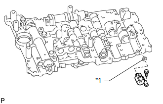
(b) Install the solenoid valve with the bolt.
Torque:
10 N·m {102 kgf·cm, 7 ft·lbf}
2. INSTALL SHIFT SOLENOID VALVE S1
.png)
(a) Install the solenoid valve with the bolt.
Torque:
6.4 N·m {65 kgf·cm, 57 in·lbf}
3. INSTALL SHIFT SOLENOID VALVE SL1
.png)
4. INSTALL SHIFT SOLENOID VALVE SLT
|
(a) Install the solenoid valve. |
|
.png)
(b) Install the 2 straight pins and solenoid lock plate with the bolt.
Torque:
6.4 N·m {65 kgf·cm, 57 in·lbf}
5. INSTALL SHIFT SOLENOID VALVE SL2
.png)
6. INSTALL SHIFT SOLENOID VALVE SLU
|
(a) Install the solenoid valve. |
|
.png)
(b) Install 2 straight pins and solenoid lock plate with the bolt.
Torque:
6.4 N·m {65 kgf·cm, 57 in·lbf}
7. INSTALL SHIFT SOLENOID VALVE SR
|
(a) Install the solenoid valve with the 2 bolts. Torque: 6.4 N·m {65 kgf·cm, 57 in·lbf} |
|
.png)
 Installation
INSTALLATION
PROCEDURE
1. INSTALL TRANSMISSION VALVE BODY ASSEMBLY
(a) Install the spring and check ball body.
(b) Insert the pin of the manual valve into the hole of the manual valve
...

Other materials about Toyota 4Runner:
Cellular Phone Registration Failure
CAUTION / NOTICE / HINT
NOTICE:
After replacing the navigation receiver assembly of vehicles subscribed to pay-type
satellite radio broadcasts, XM radio ID registration is necessary.
HINT:
If the operation of a cellular phone or the navigation receiver a ...
ECU Power Source Circuit
DESCRIPTION
This is the power source for the tire pressure warning ECU.
WIRING DIAGRAM
CAUTION / NOTICE / HINT
NOTICE:
When replacing the tire pressure warning ECU, read the IDs stored in
the old ECU using the Techstream and write them down ...
0.0276