Toyota 4Runner: Removal
REMOVAL
CAUTION / NOTICE / HINT
CAUTION:
Some of these service operations affect the SRS airbag system. Read the precautionary
notices concerning the SRS airbag system before servicing the steering column (See
page .gif) ).
).
PROCEDURE
1. PLACE FRONT WHEELS FACING STRAIGHT AHEAD
2. REMOVE FRONT WHEEL LH
3. REMOVE STEERING WHEEL ASSEMBLY
(a) Remove the steering wheel (See page ).
4. REMOVE STEERING COLUMN LOWER COVER
|
(a) Remove the 2 screws. |
|
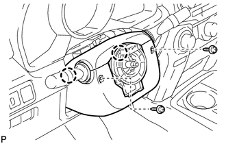
(b) Detach the 2 claws to remove the steering column lower cover.
5. REMOVE STEERING COLUMN UPPER COVER
|
(a) Detach the 4 clips. |
|
(b) Detach the claw to remove the steering column upper cover.
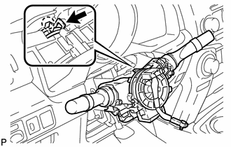
6. REMOVE COMBINATION SWITCH ASSEMBLY WITH SPIRAL CABLE SUB-ASSEMBLY
(a) Disconnect the connectors from the combination switch with spiral cable.
|
(b) Use pliers to hold the clamp and raise the claw with a screwdriver. Remove the turn signal switch assembly with spiral cable sub-assembly from the steering column assembly. |
|
7. REMOVE TRANSPONDER KEY AMPLIFIER (w/ Transponder Key)
(a) Remove the transponder key amplifier (See page
).
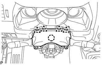
8. REMOVE NO. 1 INSTRUMENT LOWER PANEL AIRBAG ASSEMBLY
(a) Remove the instrument lower panel airbag assembly (See page
).
9. REMOVE STEERING COLUMN ASSEMBLY
(a) Detach the claws to remove the wire harness protector and wire harness.
|
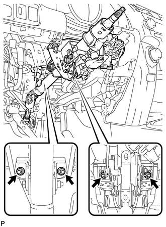
(b) Put matchmarks on the steering intermediate shaft and steering column. Text in Illustration
|
|
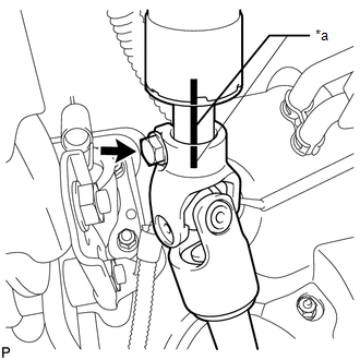
(c) Remove the bolt.
|
(d) Remove the 4 nuts and steering column. |
|
10. REMOVE NO. 1 FRONT FENDER APRON TO FRAME SEAL LH
11. DISCONNECT STEERING INTERMEDIATE SHAFT ASSEMBLY
|
(a) Put matchmarks on the steering intermediate shaft and No. 2 steering intermediate shaft. Text in Illustration
|
|
(b) Remove the bolt, and then pull out the intermediate shaft toward the inside of the vehicle.
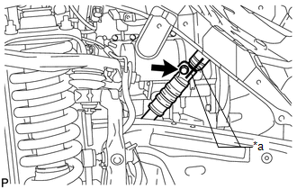
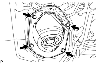
12. REMOVE NO. 1 STEERING COLUMN HOLE COVER SUB-ASSEMBLY
|
(a) Remove the 4 bolts and steering column hole cover from the vehicle. |
|
13. DISCONNECT NO. 2 STEERING INTERMEDIATE SHAFT SUB-ASSEMBLY
|
(a) Put matchmarks on the No. 2 steering intermediate shaft and power steering gear. Text in Illustration
|
|
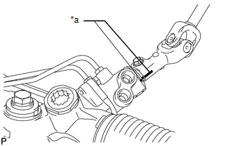
(b) Remove the bolt and No. 2 steering intermediate shaft from the power steering gear.
 Components
COMPONENTS
ILLUSTRATION
ILLUSTRATION
ILLUSTRATION
...
 Disassembly
DISASSEMBLY
PROCEDURE
1. REMOVE STEERING LOCK ACTUATOR ASSEMBLY
(a) Using a center punch, mark the center of the tapered-head bolt.
(b) Using a 3 to 4 mm (0.118 to 0.157 in.) drill, drill a hole i ...
Other materials about Toyota 4Runner:
Meter Illumination does not Dim at Night
DESCRIPTION
If the dimmer switch is turned to TAIL, HEAD or AUTO, the main body ECU sends
a TAIL relay signal, panel light illumination signal, panel relay signal and TAIL
cancel OFF signal to the combination meter. Then the meter and accessory meter beco ...
How To Proceed With Troubleshooting
CAUTION / NOTICE / HINT
HINT:
Inspect the window defogger system after confirming that the back door
power window system of the power window control system is operating normally.
Use these procedures to troubleshoot the window defogger sys ...
0.0097